
The transmitter has four proportional channels, which means the controlled surfaces will move proportionally to the movements of the Control Sticks. These proportional channels are usually assigned to channels 1 through 4 as default. Depending on the selected Control Stick Mode, the channel's mapping to each stick will be different as explained in the below images. Additional channels (5 through 12) are controlled by switches, sliders or knobs and are used to control the operation of landing gear, flaps, airbrakes etc.
The AT10II incorporates Five Control Stick modes(-,1,2,3,4). The default mode is selected by the consumer at the time of purchase. The following displays indicate the available mode layouts.
Mode 5 "-" is custom programmable mode. This mode allows the user to program AUX channels to the left or right stick functionality (replacing the default CH1 to 4)
Note: This section explains the necessary steps to mechanically change the gimbal locations. The Mode Function must be programmatically changed to suit the new gimbal layout. Please refer to STK-MODE for software changes.

1. To change the Mode layout of the gimbals, remove the back cover from the transmitter by removing the battery cover, battery pack(or tray) and the four #1 Phillip head scews holding the back cover to the main case.
 Do not lay the transmitter on the gimbal sticks(control sticks). This may damage the gimbal's components which could result in an uncontrolled flight characteristic.
Curcuit boards contain static sensitive compotents. Discharge any static electricity from your hands by touching a proper ground device before working or touching a circuit board.
2. Slowly remove the back cover by lifting it slightly and then laying it beside the main case. Locate the Trainer Port Wire cable coming from the back cover and disconnect its connector which is located in the middle of the main circuit board, then set the cover off to the side.
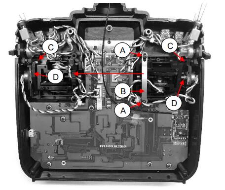
3. To switch gimbal modes, remove the Tension Plate's two #1 Phillip Head srcews[A] and then the Tension Plate[B].
- Relocate the Tension Plate to the othe gimbal and install the plate using the same screws.
4. Next, using tweezers(or smilar tool) remove the Lever Arm Spring[C] and then the Lever Arm[D] by gently lifting it back and upwards.
- Relocate the Lever Arm Spring and Lever Arm to the other gimbal and reinstall them in the same manner.
5. Adjust the sticks' tensions as needed.
6. Reconnect the trainer's port wire lead then reinstall the back cover.
7. Proceed to changing the software setting for the mode position:
Long press the Mode key to enter the BASIC MENU->Rotate the Scroll Dial to highlight the PARAMETER option and depress the Enter key->Select the STK-MODE and change the Mode as required.
8. Finally perform a Control Stick Calibration to ensure accuracy. https://www.youtube.com/watch?v=cbXGhqQ-SBw


 RadioLink Products Instruction Manual Download