


RADIOLINK T8FB Firmware Upgrade or Model Type Change
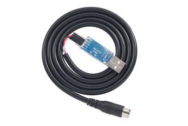
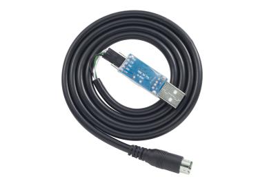
Upgrade/firmware version change/parameter setting cable
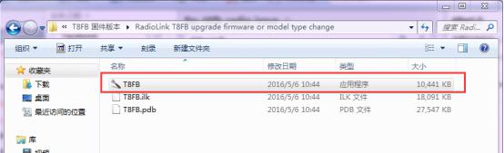
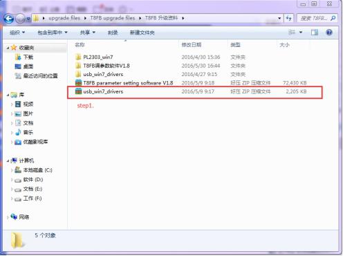
1.Install the T8FB upgrade drive files first.
2.Connection: One end of T8FB USB cable connect to computer and the other end connect to the upgrade port which at the back of T8FB.
T8FB upgrade connector connection:
TXD connect to white wire, RXD connect to red wire, GND connect to black wire.
OR TXD connect to white wire, RXD connect to green wire, GND connect to black wire.
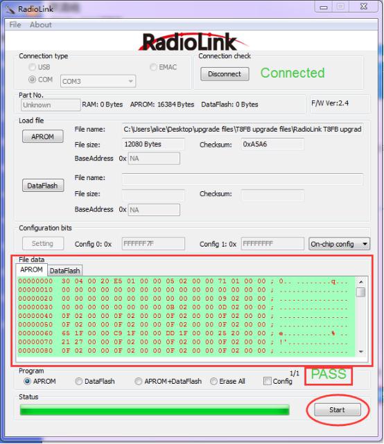
1.Open file “T8FB”.
2.Choose COM, and click “Connect” and then turn on T8FB in 1 second.

3.“Disconnect” will change to “Connected” and the color of word will from red to green if connect successful.

4.Choose “APROM” and then choose the firmware you need, for example, firmware for multicoptor.
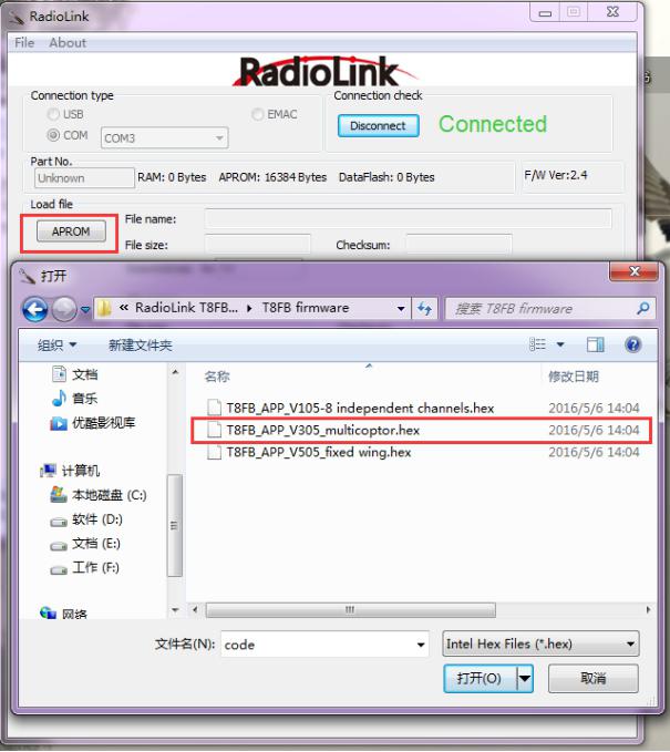
Attention:
V105 for independent 8 channels
V305 for multicoptor(CH5 will controlled by SwA and SwB to set six flight mode such as connect to PIX or APM flight controller)
V505 for fixed wing
5.Click “Start”, the progress bar will turn to green, upgrade successful if remind “PASS”.
Part 3 Parameter Configuration
2.1 Preparation
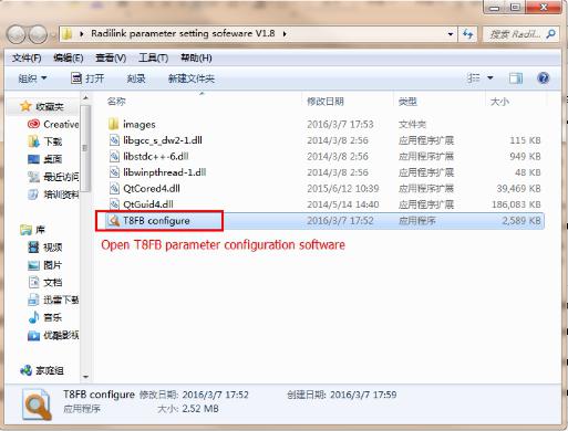
1. Install the drive for the parameter configuration software.
Open T8FB parameter configuration software.
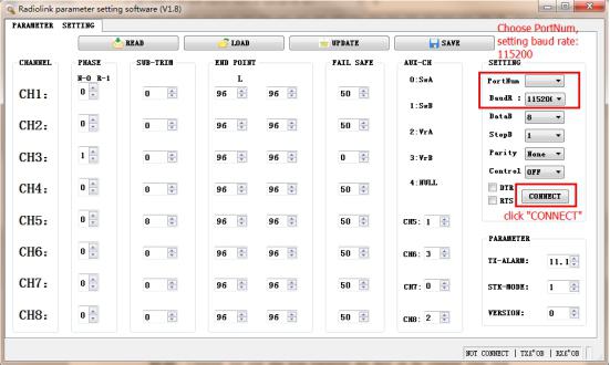
2. Choose Port Number(T8FB connection COM will automatic identified when connect to computer), setting baud rate: 115200, 8-1-None(8 data bits,1 stop bit,no parity check),click “CONNECT”.
2.2 Software description
“READ”:
Computer will read data from transmitter and show on the computer when click “READ”(red and green LED will quick flashing when reading).
“LOAD”:
Load configured TXT files.
“UPDATE”:
Write down the new data you want and then click “UPDATE” to change the defaulted parameter. T8FB will remember the new data you have write down(red and green LED will slowly flashing when updating).
“SAVE”:
Save current setting to TXT files.
“PHASE”:
Changes the direction an individual servo responds to a control stick motion.
“SUB-TRIM”:
Makes small changes or corrections to the neutral position of each servo. Range is -120 to +120, with 0 setting, the default, being no SUB-TRIM.
We recommend that you center the digital trims before making SUB-TRIM changes, and that you try to keep all of the SUB-TRIM values as small as possible. Otherwise, when the SUB-TRIM are large values, the servo's range of travel is restricted on one side.
The recommended procedure is as follows:
• Measure and record the desired surface position;
• Zero out both the trims (TRIM RESET menu) and the SUB-TRIM (this menu);
• Mount servo arms and linkages so that the control surface’s neutral is as correct as possible;
•use a small amount of SUB-TRIM to make fine corrections.
“END POINT”:
Sets the range of each channel(in percentage);
End Point of servo travel adjustment (END POINT, also called EPA)
The most flexible version of travel adjustment is available. It independently adjusts each end of each individual servo’s travel, rather than one setting for the servo affecting both directions.
Adjustability:
• Can set each direction independently.
• Ranges from 0% (no servo movement at all) to 140%. Defaulted 96%.
•Reducing the percentage settings reduces the total servo throw in that direction.
END POINT adjusts only the individual servo. It will have no effect on any other servo that is operated in conjunction with this servo via mix or preset programming such as FLAPERON,
AILEVATOR, etc. This is so that each individual servo can be carefully fine-turn to avoid binding and other conflicts. To adjust the total travel of a function such as FLAPERON, make the adjustments in that function's controls.
The higher the END POINT setting, the better position accuracy and the more servo power available at nearly any position (except if using digital servos). Higher END POINT values also mean longer travel time to reach the desired position, as you are utilizing more of the servo's total travel. (For example, using 50% END POINT would give you only half the steps of servo travel, meaning every click of trim has twice the effect and the servo gets there in half the time).
• END POINT(and moving the linkage) = torque, accuracy, but transit time to get there.
• END POINT (instead of adjusting linkages) = travel time, but torque, accuracy.
“FAIL SAFE”:
F/S data,set responses in case of loss of signal or low Rx voltage(in percentage).
Each channel can be set independently.
• The NOR (normal) setting holds the servo in its last commanded position.
• The F/S (Fail Safe) function moves each servo to a predetermined position.
• NOTE: the setting of the throttle's F/S also applies to the low battery voltage.
• The F/S is used in certain competitions to spin the aircraft to the ground prior to flying away and doing potential damage elsewhere. Conversely, may also be used to go to neutral on all servos, hopefully keeping the plane flying as long as possible.
0 means throttle at the lowest position, 50 at the center position.
“AUX-CH”:
Defines the relationship between the transmitter controls and the receiver output for channels 5-8.
“TX-ALARM”:
Setting transmitter alarm voltage(defaulted 11.1 V).
“STK-MODE”:
Change the mapping relation among sticks(MODE1 means throttle is the right stick; MODE2 means throttle is the left stick).


 Radiolink FQA