
Disclaimer and Warning
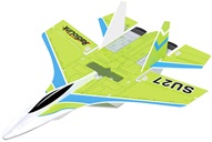
Thank you for purchasing RadioLink fixed-wing SU27.
To fully enjoy the benefits of this product and ensure safety, please read the manual carefully and set up the device as instructed steps. This product is not a toy and is NOT suitable for children under the age of 14. Adults should keep the product out of the reach of children and exercise caution when operating this product in the presence of children.
Inappropriate operation may cause property loss or accidental threats to life. Once the RadioLink product is operated, it means the operator understands this limitation of liability and accepts to take responsibility for the operation.
Make sure to follow the local laws and agree to follow the principles made by RadioLink.
Fully understand that RadioLink cannot analyze the product damage or accident reason and cannot offer after-sales service if no flight record is provided. To the maximum extent permitted by law, RadioLink won't take any responsibility for the loss caused by indirect/consequent/accidental/special/penal damages including the loss by purchase, operation, and failure of operation in any instances. Even RadioLink is informed about the possible loss in advance.
Laws in certain countries may prohibit the exemption from the terms of the guarantee. Therefore, consumer rights in different countries may vary.
In compliance with laws and regulations, RadioLink reserves the right to interpret the above terms and conditions. RadioLink reserves the right to update, change, or terminate these terms without prior notice.
Warning
1. Please do not fly in the rain! Rain or moisture may cause flight instability or even loss of control. Never fly if there is lightning. It is recommended to fly in conditions with good weather (No rain, fog, lightning, wind).
2. When flying, you must strictly abide by local laws and regulations and fly safely! Do not fly in no-fly areas such as airports, military bases, etc.
3. Please fly in an open field away from crowds and buildings.
4. Do not perform any operation under the condition of drinking, fatigue, or other poor mental state. Please operate in strict accordance with the product manual.
5. Please be cautious when flying near electromagnetic interference sources, including but not limited to high-voltage power lines, high-voltage transmission stations, mobile phone base stations, and TV broadcast signal towers. When flying in the above-mentioned places, the wireless transmission performance of the remote control may be affected by interference. If there is too much interference, the signal transmission of the remote control and the receiver may be interrupted, resulting in a crash.
Packing List
Items | Details | Picture | PNP | RTF |
Fuselage | Polypropylene (PP), 400mm wingspan, 478mm length, 116g weight |
| 1 | 1 |
Transmitter | RadioLink T8S 1 |
| 0 | 1 |
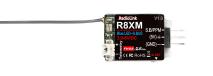
Receiver | RadioLink R8XM |
| 0 | 1 |
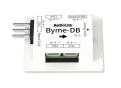
Flight Controller | RadioLink Byme-DB |
| 1 | 1 |
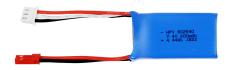
Battery | HPY 2S 7.4V 600mAh lithium battery |
| 1 | 1 |
Motor | SZ-SPEED 1306-4000KV brushless motor |
| 1 | 1 |
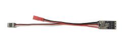
ESC | FLYCOLOR 15A brushless ESC |
| 1 | 1 |
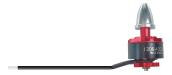
Propeller | GEMFAN 3052 propellers, dia. 76.2mm |
| 2 | 2 |
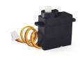
Servo | 4.3g servos |
| 2 | 2 |
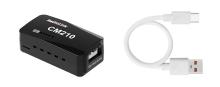
Charger | RadioLink balance charger CM210 for 2S LiPo Battery |
| 0 | 1 |
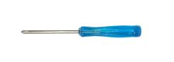
Other Accessories | 2.0 crossscrewdriver |
| 1 | 1 |
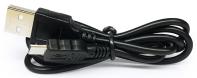
Charging&update cable for T8S |
| 0 | 1 | |
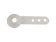
Spare Rudder Angle |
| 1 | 1 | |
| 1 | 1 | ||
Instruction manual |
| 1 | 1 | |
Packaging (Choose one) | Shoulder bag |
| 1 | 1 |
Colorful box |
|
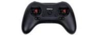


Annotation 1: T8S is used as an example in the SU27 manual. Users can choose other RadioLink transmitters and receivers to control SU27. Optional RadioLink transmitters include T8S, T8FB, T16D, AT9S Pro, and AT10II.
Note: Please refer to the sales interface for the actual packing list.
Chapter 1 SU27 General Introduction
1.1 SU27 Overview
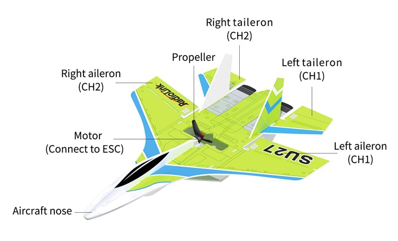
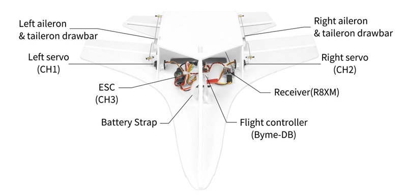
1.2 Usage of SU27 Units
1.2.1 Notice for Use
No foreign matter such as water, oil, sand, etc. inside the SU27.
Make sure the complete device includes. SU27 and transmitter, battery functions well.
Never self-change the aircraft or related parts. Or it may influence its functionality and possibly cause flight accidents.
1.2.2 Receiver Connection
For the SU27 PNP version, the transmitter and receiver need to be installed. SU27 is compatible with all receivers that support SBUS/PPM signals.
1. First, install the receiver on the SU27 aircraft. Make sure the receiver is switched to SBUS/PPM signal mode, and then connect the receiver to the Byme-DB flight controller. For the connection method of the receiver, please refer to Chapter 1.2.3 Flight Controller.
Note: Byme-DB comes with a receiver connect cable which is used to connect the receiver to Byme-DB. When connecting the servo cable and ESC cable to Byme-DB, please check whether the servo cable and ESC cable match the sockets/head of Byme-DB. If they do not match, the user needs to modify the servo cable and ESC cable, and then connect the cables to Byme-DB.
Byme-DB Socket Specifications: CH1, CH2 and CH4 are with 3P SH1.00 sockets; The receiver connect socket is 3P PH1.25 socket; CH3 is with a 3P 2.54mm Dupont Head
2. Second, calibrate the throttle range of the SU27 ESC. The normal Start-up and Throttle Range calibration steps of SU27 ESC are as follows:
① Turn on the transmitter. Toggle the switch of CH7 to unlock the motor, and then move the throttle stick to the top position.
② Connect the battery to the ESC and wait for the motor to emit a short beep, which means the full throttle position is memorized.
③ After the flight controller self-check is completed, move the throttle stick to the bottom position, and the motor will make a short beep, indicating that the "zero throttle" position is memorized.
④ The ESC calibration is complete and SU27 is ready to take off at any time.
For more information on how to use SU27 ESC, please visit RadioLink's official website: https://www.radiolink.com/manuals_download
1.2.3 Flight Controller Byme-DB
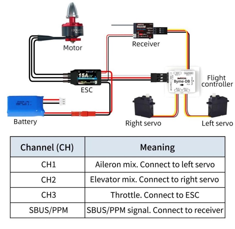
SU27 is installed with the flight controller Byme-DB by default. When installing or replacing the flight controller, make sure the arrow on Byme-DB points to the aircraft head. Use 3M glue to flatly attach Byme-DB to the fuselage. It is recommended to install it near the center of gravity of the aircraft. If the flight control is not installed stably, the aircraft will vibrate abnormally when flying in stabilize and gyro modes. Refer to the picture below to connect the flight controller, servos, receiver, ESC, motor, and battery.
1.2.4 Motor
The motor installed on SU27 is an SZ-SPEED 1306-4000KV brushless motor. (Motor with higher KV value, means higher rotation speed and smaller torsion force; Motor with lower KV value, means lower rotation speed and larger torsion force.)
Usage of Motor:
1. Make sure the motor is installed tightly and rotates smoothly. If fails to rotate, stop operating the transmitter immediately and pull the throttle to the bottom position in case of possible damage to the motor.
2. Never self-change the motor structure.
3. When the motor stops rotating, never touch it at once, otherwise may get burnt.
4. Never cover the air vent on the motor. Make sure no foreign matter is inside the motor.
5. Make sure the motor completely stops before powering off the SU27 and the transmitter.
1.2.5 ESC
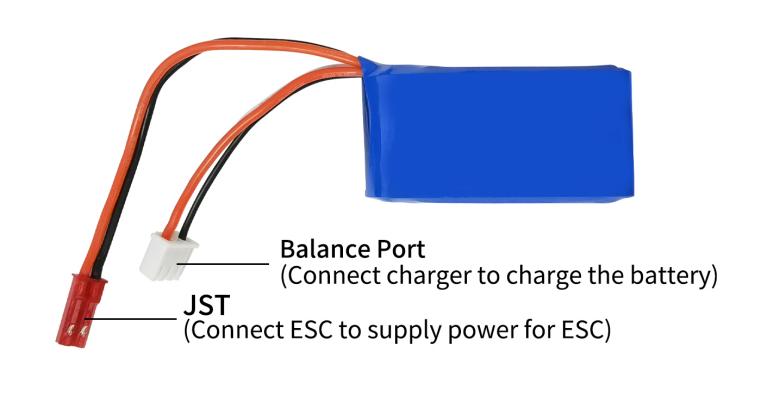
The function of ESC is to change the direct current to alternating one to power supply motor and change its rotation speed based on the throttle command. Another function of ESC is to lower the model voltage to 5V for a receiver as the battery applied for SU27 supports 7.4V-8.4V working voltage. Therefore, there are three wires of ESC for battery, motor, and receiver. ESC applied in SU27 is 15A brushless ESC.
Usage of ESC:
Make sure there's a tone from ESC when powering on the aircraft.
1.2.6 Servo
SU27 uses 4.3g servos and two servos are installed on the left and right sides of the fuselage.
1.2.7 Propeller
SU27 is packed with 2 positive propellers by factory default. If a new propeller needs to be changed, you need to distinguish the front and back sides of the propeller. If the front and back sides of the propeller are installed incorrectly, the aircraft can't take off even to maximize the throttle. The propeller with words should face the nose of SU27. The rotation direction of the motor and propeller should be the same. That is, if the motor rotates clockwise, so does the propeller.
Usage of propeller:
- Make sure to check the propeller is in good condition before flight. If aged, damaged, or deformed, please change to a good one then fly.
- Make sure to disconnect the power supply before touching the propeller.
- As the propeller is thin, use tools to (un)install it if necessary and be careful to avoid accidental scratches.
- Make sure the propeller is installed well and tight before flight.
- Do not get close to the rotating propeller and motor (for example, to pick up a landing plane by hand ) to avoid cuts.
1.2.8 Battery
SU27 supports a 2S-3S LiPo battery. SU27 is packed with 2S 7.4V 600mAh LiPo Battery.
Usage of battery:
- Make sure the power connection of the transmitter and aircraft is dry.
- Make sure the transmitter and aircraft are fully charged.
- When the transmitter emits DDD beeps to alarm low battery voltage, if the power of the aircraft drops when the throttle is pushed, the battery voltage on the aircraft is insufficient. At this time, please return to the flight immediately to avoid the failure of the aircraft to return due to the insufficient power battery voltage and the over-discharge of the battery.
Chapter 2 Flight Modes Setup
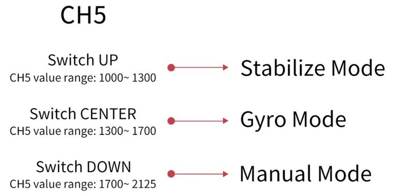
Flight modes oF SU27 can be set to channel 5 (CH5) (a 3-way switch) in the transmitter with 3 modes: Stabilize Mode, Gyro Mode, and Manual Mode.
When using other brand transmitters, please refer to the following picture to switch the flight modes. The value range of channel 5 (CH5) corresponding to the flight mode is as shown below:
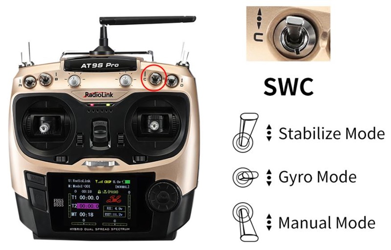
Take the RadioLink AT9S Pro transmitter as an example. Flight modes are set by CH5 (3-way switch, SWC) as below:
Chapter 3 Motor Safety Lock
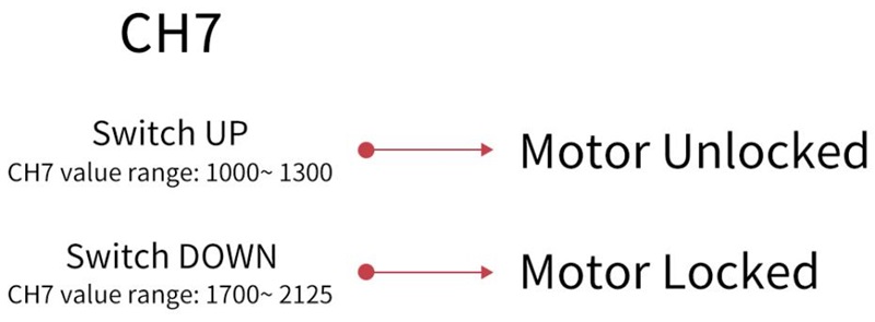
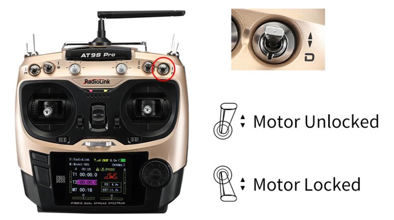
The motor can be locked/unlocked by Channel 7 (CH7) in the transmitter, so please use the transmitter with 7 channels or above
When the motor is locked, the motor will not rotate even if the throttle stick is in the highest position. Please put the throttle to the lowest position, and toggle the switch of channel 7 (CH7) to unlock the motor. The motor emits two long beeps means the unlocking is successful. When the motor is locked, the gyro of Byme-DB is automatically turned off; When the motor is unlocked, the gyro of Byme-DB is automatically turned on.
Note: If the motor only beeps once when toggle the switch of channel 7 (CH7) to the unlock position, the unlocking fails. Please follow the methods below to troubleshoot it.
1. Check whether the throttle is at the lowest position. If not, please push the throttle to the lowest position until the motor emits a second-long beep, which means the unlocking is successful.
2. Since the PWM value width of each transmitter may be different when using other transmitters except RadioLink T8FB/T8S if the unlocking still fails even though the throttle is at the lowest position, you need to increase the throttle travel in the transmitter. You can toggle the switch of channel 7 (CH7) to the motor unlocking position, and then adjust the throttle travel from 100 to 101, 102, 103... until you hear the second long beep from the motor, which means the unlocking is successful. During the process of adjusting the throttle travel, be sure to stabilize the fuselage to avoid injuries caused by blade rotation.
When using other brand transmitters, please refer to the following picture to lock/unlock the motor. The value range of channel 7 (CH7) is as shown below:
Take the RadioLink AT9S Pro transmitter as an example. The motor lock is controlled by CH7 (2-way switch, SWD) as below:
Chapter 4 Transmitter Setup
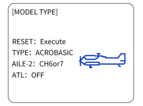
4.1 Model Type Setup
For the SU27 PNP version, the model type needs to be set as a fixed-wing in the transmitter. Take AT9S Pro as example( same as AT10II/AT9S/AT10/AT9).
Steps: Power on the transmitter - Long press Mode to enter BASIC MENU - Turn the Dial to MODEL TYPE - Press Push to enter the menu and turn Dial to select ACROBASIC - Long press Push for 1 second and a notice “ARE YOU SURE” pops out - Press Push again and a notice” Please wait...” pops out and there will be DEE sound heard, meaning setting complete.
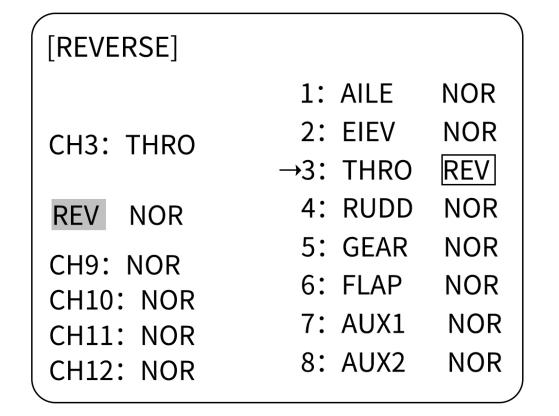
4.2 Transmitter Phase Setup
When using a non-RadioLink transmitter, there is no need to set the transmitter phase.
Please set the direction of CH3 to Reverse, and other channels CH1/CH2/CH4 to Normal. Take AT9S Pro as an example (same as AT10II/AT9S/AT10/AT9).
Steps: Long press Mode to enter BASIC MENU - rotate Dial to REVERSE - Press Push to enter the menu - rotate Dial to 3:THRO - change NOR to REV - Long press Push for 1 second to confirm.
Note: Do not set any mixing in the transmitter when Byme-DB is mounted on the aircraft. Because there is already the mixing in Byme-DB. The mix control will automatically take effect according to the flight mode of the aircraft. If the mixing function is set in the transmitter, there will be conflicts of mixing and affect the flight.
Chapter 5 Flight Precautions
- Check before take-off to make sure that all parts are in good working condition.
- Make sure the battery is fully charged and properly bound to the fuselage before take-off.
- Make sure that the front and back of the propeller are installed correctly and the propeller is not inclined.
- After the setting channel direction in the transmitter, please calibrate the attitude once. Then check the servo phase. Push the joystick to check whether the movement of the control surface is correct. If it is not, please change the direction of the corresponding channel on the flight controller.
- After the motor is unlocked, the gyro function is automatically turned on. Hold the SU27 in your hand and swing it, without operating the joystick of the transmitter. If there is no movement on the control surface, it is in manual mode. If the control surfaces move as the fuselage swings, it is stabilize mode or gyro mode.
- It is recommended to change to another battery to avoid over-discharge of the battery when the transmitter emits DDD beeps to alarm low battery voltage.
- If there is any abnormality during the flight, please land immediately and find out the reason.
Chapter 6 Power-on and Gyro Self-test
Each time SU27 is powered on, the gyro of the flight controller will perform a self-test. The gyro self-test can only be completed when the aircraft is stationary. It is recommended to install the battery first, then power up the aircraft and keep the aircraft in a stationary state. After the aircraft is powered on, the green indicator light on channel 3 will be always on. When the gyro self-test passes, the control surfaces of the aircraft will shake slightly, and the green indicator lights of other channels such as channel 1 or channel 2 will also turn solid.
Note:
- Due to differences in aircraft, transmitters, and other equipment, it is possible that the green indicators of other channels (such as channel 1 and channel 2) will not be on after the gyro self-test of Byme-DB is complete. Please judge whether the self-test is complete by checking whether the control surfaces of the aircraft shake slightly.
- Push the throttle stick of the transmitter to the lowest position first, and then power on the aircraft. If the throttle stick is pushed to the highest position and then powered on the aircraft, the ESC will enter the calibration mode.
Chapter 7 Attitude Calibration
Flight controller Byme-DB needs to calibrate the attitudes/level to ensure the balance status.
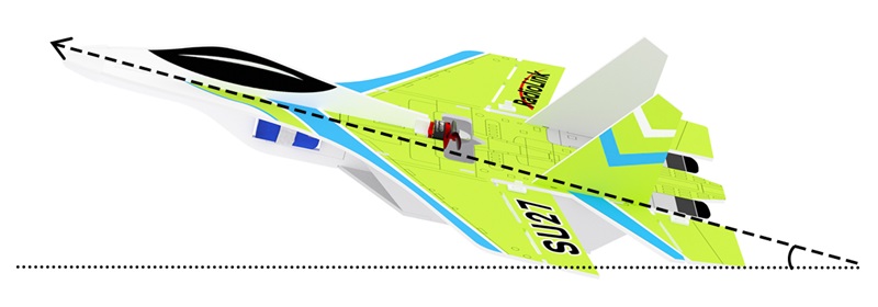
The aircraft can be placed flat on the ground when performing attitude calibration. It is advised to lift the model head with a certain angle (20 degrees is advised) for beginners to ensure smooth flight and attitude calibration will be recorded by the flight controller once it is complete with success.
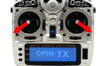
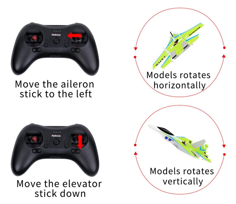
Push the left stick (left and down) and the right stick (right and down) as below and hold for more than 3 seconds. The green LED flashes once means the calibration is completed.
Note: When using a non-RadioLink transmitter, if the attitude calibration is unsuccessful when pushing the left stick (left and down) and the right stick (right and down), please change the direction of the channel in the transmitter. Make sure when pushing the joystick as above, the value range of channel 1 to channel 4 is: CH1 2000 µs, CH2 2000 µs, CH3 1000 µs, CH4 1000 µs
Take an open-source transmitter as an example. The servo display of channel 1 to channel 4 when calibrating the attitude successfully is as shown below:
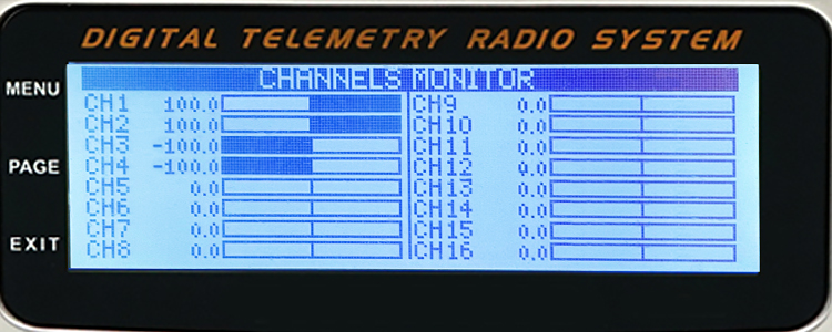
CH1 2000 µs (opentx +100), CH2 2000 µs (opentx +100)
CH3 1000 µs (opentx -100), CH4 1000 µs (opentx -100)
Chapter 8 Servo Phase
8.1 Servo Phase Test
Please complete the attitude calibration in Chapter 7 first. And then test the servo phase. Otherwise, the control surface may swing abnormally.
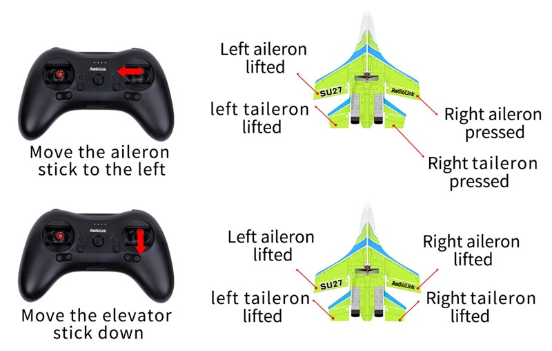
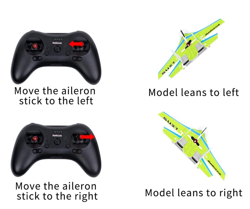
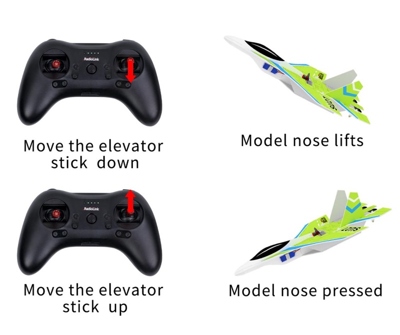
Toggle the switch of CH5 to Manual mode. Then check if the the movement direction of the ailerons/tailerons is consistent with the joystick movement. Take Mode 2 for the transmitter as an example.
8.2 Servo Phase Adjustment
When the movement direction of the ailerons is inconsistent with the joystick movement, please adjust the servo phase by pressing the buttons on the front of the Byme-DB.
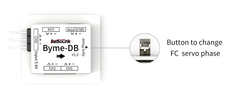
Servo phase adjustment methods:
Servo phase test result | Reason | Solution | LED |
Move the aileron stick to the left, and the movement direction of the ailerons and tailerons is reversed | Aileron mix control reversed | Short press the button once | Green LED of CH1 on/off |
Move the elevator stick down, and the movement direction of the ailerons and tailerons is reversed | Elevator mix control reversed | Short press the button twice | Green LED of CH2 on/off |
Move the rudder joystick, and the movement direction of the rudder servo is reversed | Channel 4 reversed | Short press the button four times | Green LED of CH4 on/off |
Note:
- The Green LED of CH3 is always on.
- Neither the always-on nor off-green LED means a reversed phase. Only toggle the joysticks can check if the corresponding servo phases are reversed. If the servo phase of the flight controller is reversed, adjust the servo phase by pressing the buttons on the flight controller. No need to adjust it in the transmitter.
Chapter 9 Three Flight Modes
Flight modes can be set to channel 5 (CH5) in the transmitter with 3 modes: Stabilize Mode, Gyro Mode, and Manual Mode. Here is the introduction of the three flight modes. Take Mode 2 for the transmitter as an example.
9.1 Stablize Mode
Stabilize Mode with flight controller balancing, is suitable for beginners to practice level flight.
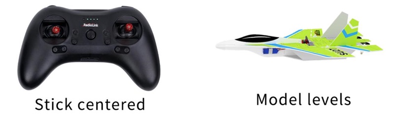
The model attitude (inclination angles) is controlled by joysticks. When the joystick is back to a central point, the aircraft will level. The max inclination angle is 70° for rolling while that for pitching is 45°.
9.2 Gyro Mode
The joystick controls the rotation (angle speed) of the aircraft. The integrated three-axis gyro assists in increasing the stability.
(Gyro mode is the advanced flight mode. The aircraft won't level even when the joystick is back to the central point.
9.3 Manual Mode
With no assistance from the flight controller algorithm or gyro, all flight movements are realized manually, which requires the most advanced skills. In Manual mode, it is normal that there is no movement of the control surface without any operation on the transmitter because there is no gyroscope involved in stabilize mode.
Chapter 10 Gyro Sensitivity
There is a certain stability margin for the PID control of Byme-DB. For aircraft or models of different sizes, if the gyro correction is insufficient or the gyro correction is too strong, pilots can try adjusting the rudder angle to adjust the gyro sensitivity.
Thank you again for choosing RadioLink products.
If the above communication cannot solve your problem, you can also send emails to our technical support: after_service@radiolink.com.cn
Thank you again for choosing the RadioLink product.