
Byme-DB Introduction
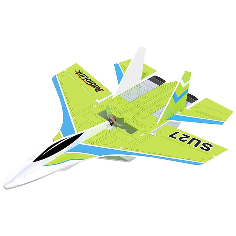
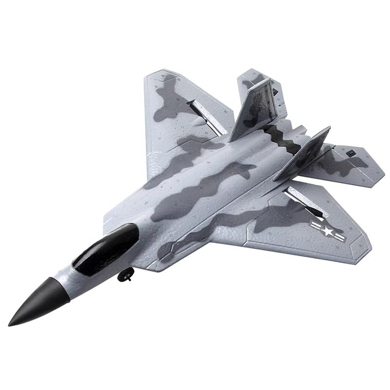
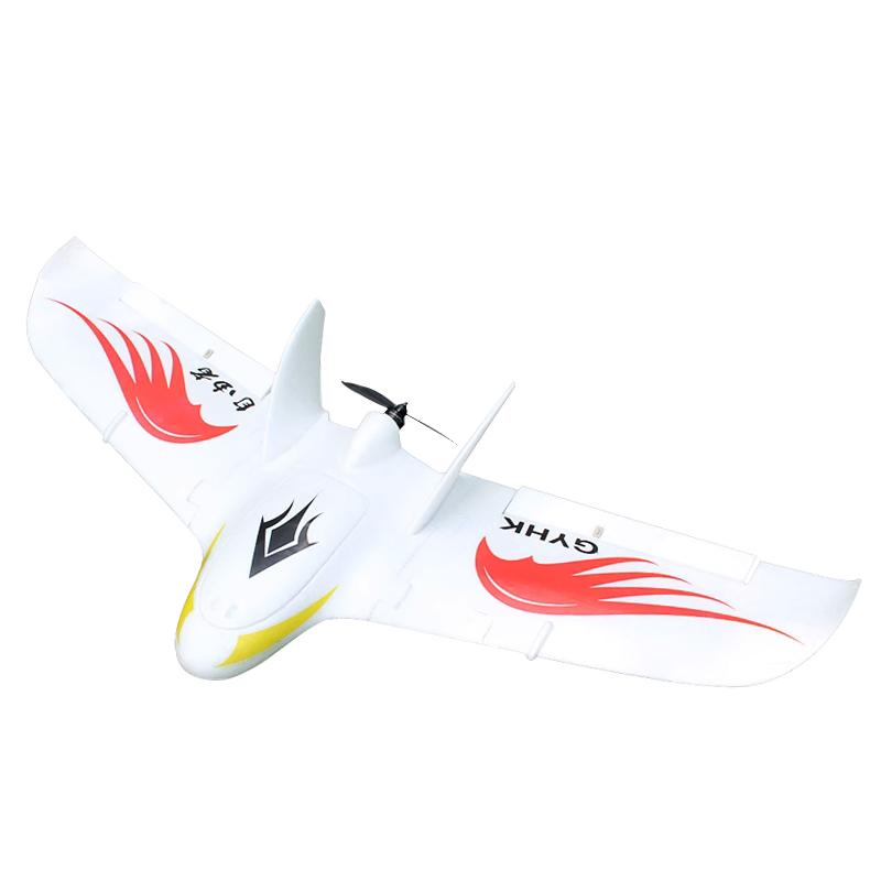
Byme-DB is applicable to all model airplanes with mixed elevator and aileron controls including delta wing, paper plane, J10, traditional SU27, the SU27 with rudder servo, and F22, etc.
Specifications
Dimension:29*25.1*9.1mm
Weight (With wires): 4.5g
Channel Quantity: 7 channels
Integrated Sensor: Three-axis gyroscope and three-axis acceleration sensor
Signal Supported: SBUS/PPM
Input Voltage: 5-6V
Operating Current: 25±2mA
Flight Modes: Stabilize Mode, Gyro Mode and Manual Mode
Flight Modes Switch Channel: Channel 5 (CH5)
Motor Lock Channel: Channel 7 (CH7)
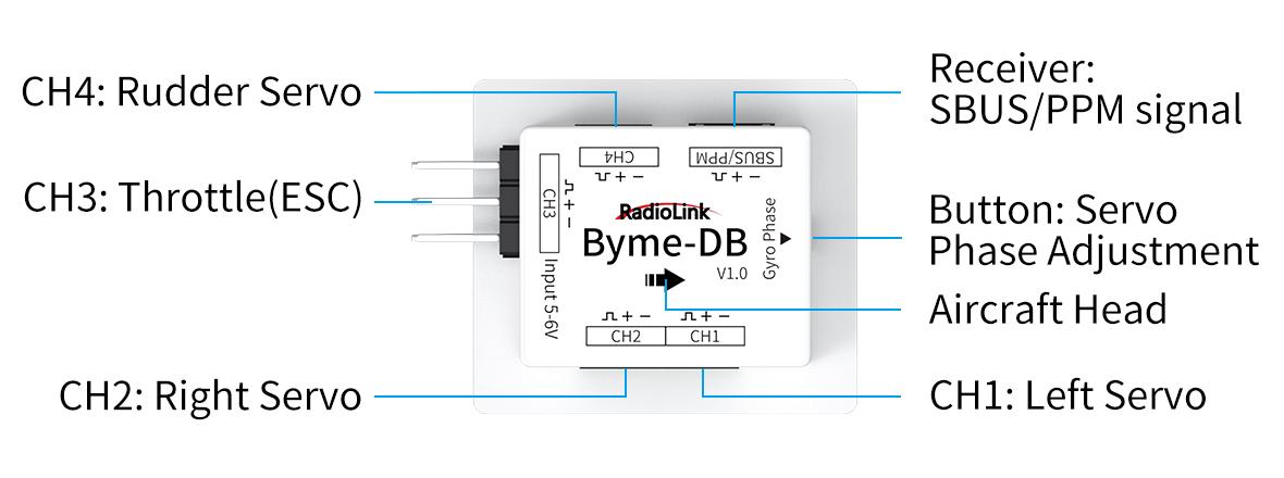
Socket Specifications: CH1, CH2 and CH4 are with 3P SH1.00 sockets; The receiver connect socket is 3P PH1.25 socket; CH3 is with a 3P 2.54mm Dupont Head
Transmitters Compatible: All the transmitters with SBUS/PPM signal output
Models Compatible:
All model airplanes with mixed elevator and aileron controls including delta wing, paper plane, J10, traditional SU27, the SU27 with rudder servo, and F22, etc.
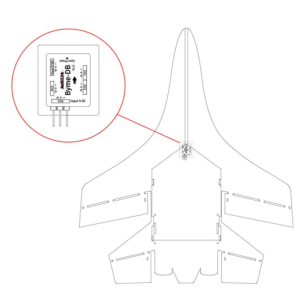
Installation
Make sure the arrow on Byme-DB points to the aircraft head. Use 3M glue to flatly attach Byme-DB to the fuselage. It is recommended to install it near the center of gravity of the aircraft. Byme-DB comes with a receiver connect cable which is used to connect the receiver to Byme-DB. When connecting the servo cable and ESC cable to Byme-DB, please check whether the servo cable and ESC cable match the sockets/head of Byme-DB. If they do not match, the user needs to modify the servo cable and ESC cable, and then connect the cables to Byme-DB.
Flight Modes Setup
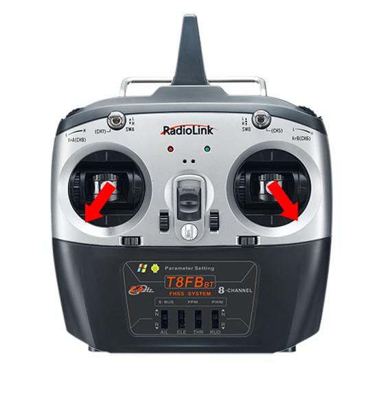
Flight modes can be set channel 5 (CH5) (a 3 way switch) in the transmitter with 3 modes: Stabilize Mode, Gyro Mode and Manual Mode. Take RadioLink T8FB/T8S transmitters as examples:
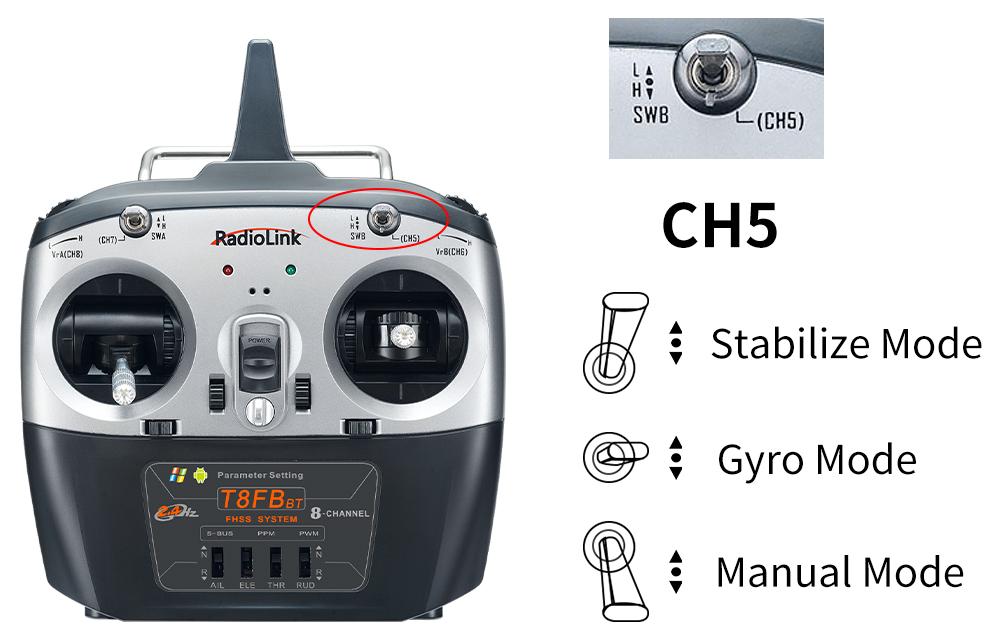
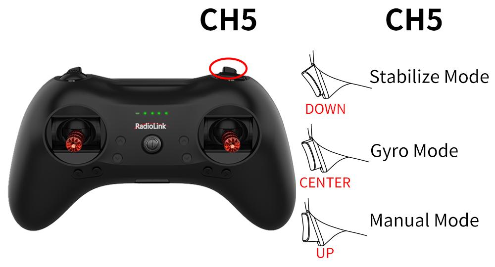
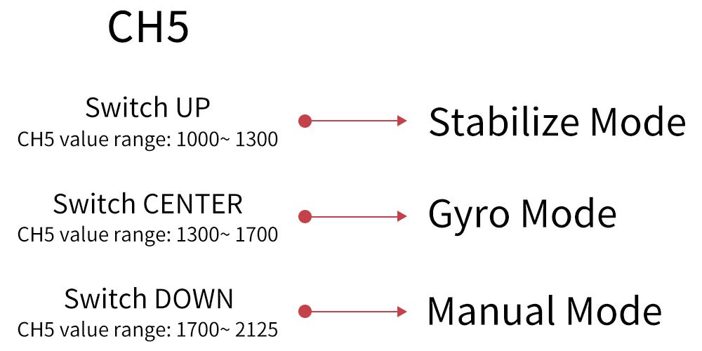
Note: When using other brand transmitters, please refer to the following picture to switch the flight modes. The value range of channel 5 (CH5) corresponding to the flight mode is as shown below:
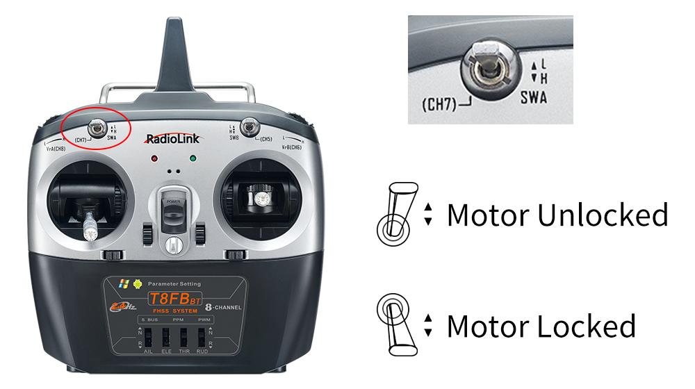
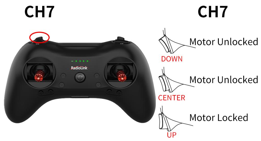
Motor Safety Lock
The motor can be locked/unlocked by Channel 7 (CH7) in the transmitter.
When the motor is locked, the motor will not rotate even if the throttle stick is in the highest position. Please put the throttle to the lowest position, and toggle the switch of channel 7 (CH7) to unlock the motor. The motor emits two long beeps means the unlocking is successful. When the motor is locked, the gyro of Byme-DB is automatically turned off; When the motor is unlocked, the gyro of Byme-DB is automatically turned on.
Note:
If the motor only beeps once when toggle the switch of channel 7 (CH7) to the unlock position, the unlocking fails. Please follow the methods below to troubleshoot it.
Check whether the throttle is at the lowest position. If not, please push the throttle to the lowest position until the motor emits a second long beep, which means the unlocking is successful.
Since the PWM value width of each transmitter may be different, when using other transmitters except RadioLink T8FB/T8S, if the unlocking still fails even though the throttle is at the lowest position , you need to increase the throttle travel in the transmitter. You can toggle the switch of channel 7 (CH7) to the motor unlocking position, and then adjust the throttle travel from 100 to 101, 102, 103... until you hear the second long beep from the motor, which means the unlocking is successful. During the process of adjusting the throttle travel, be sure to stabilize the fuselage to avoid injuries caused by blade rotation.
Take RadioLink T8FB/T8S transmitters as examples:
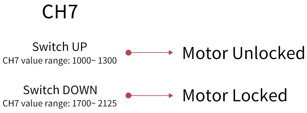
Note: When using other brand transmitters, please refer to the following picture to locked/unlock the motor. The value range of channel 7 (CH7) is as shown below:
Transmitter Setup
Do not set any mixing in the transmitter when Byme-DB is mounted on the aircraft. Because there is already the mixing in Byme-DB. The mix control will automatically take effects according to the flight mode of the aircraft. If the mixing function is set in the transmitter, there will be conflicts of mixing and affect the flight.
If RadioLink transmitter is used, set transmitter phase:
Channel 3 (CH3) - Throttle: Reversed
Other channels: Normal
Note: When using a non-RadioLink transmitter, there is no need to set the transmitter phase.
Power-on and Gyro Self-test
Each time the flight controller is powered on, the gyro of the flight controller will perform self-test. The gyro self-test can only be complete when the aircraft is stationary. It is recommended to install the battery first, then power up the aircraft and keep the aircraft in a stationary state. After the aircraft is powered on, the green indicator light on channel 3 will be always on. When the gyro self-test passes, the control surfaces of the aircraft will shake slightly, and the green indicator lights of other channels such as channel 1 or channel 2 will also turn solid.
Note:
1. Due to differences in aircraft, transmitters and other equipment, it is possible that the green indicators of other channels (such as channel 1 and channel 2) will not be on after the gyro self-test of Byme-DB is complete. Please judge whether the self-test is complete by checking whether the control surfaces of the aircraft shake slightly.
2.
Push the throttle stick of the transmitter to the lowest position first, and then power on the aircraft. If the throttle stick is pushed to the highest position and then power on the aircraft, the ESC will enter the calibration mode.
Attitude Calibration
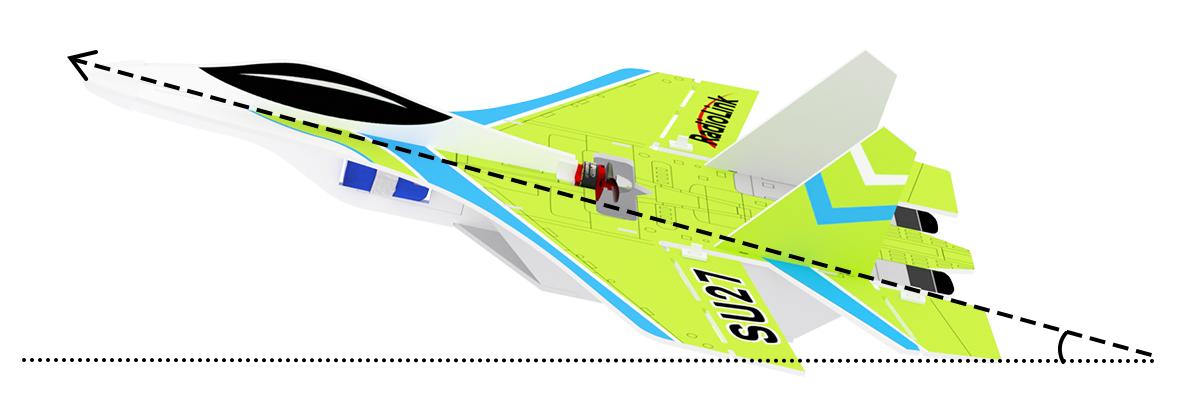
Flight controller Byme-DB needs to calibrate the attitudes/level to ensure the balance status.
The aircraft can be placed flat on the ground when performing attitude calibration. It is advised to lift the model head with a certain angle(20 degree is advised) for beginner to ensure smooth flight and attitude calibration will be recorded by flight controller once the it is complete with success.
Push the left stick (left and down) and the right stick (right and down) as below and hold more than 3 seconds. The green LED flashes once mean the calibration completed.
Note: When using a non-RadioLink transmitter, if the attitude calibration is unsuccessful when pushing the left stick (left and down) and the right stick (right and down), please change the direction of the channel in the transmitter. Make sure when pushing the joystick as above, the value range of channel 1 to channel 4 is:
CH1 2000 µs, CH2 2000 µs, CH3 1000 µs, CH4 1000 µs
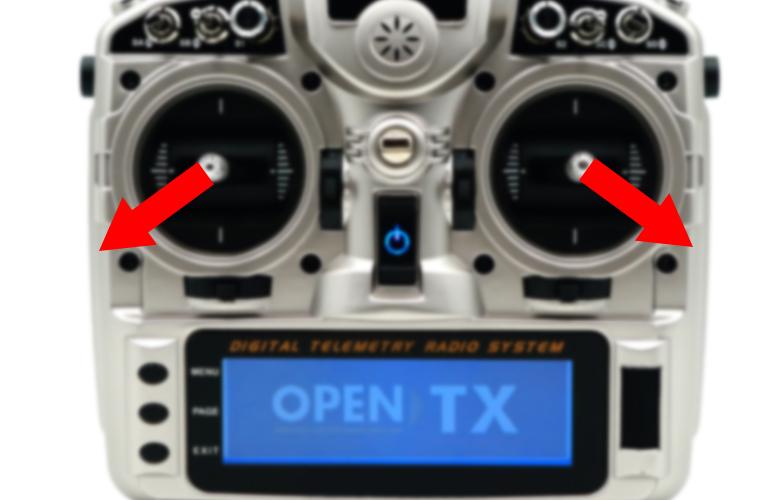
Take an open source transmitter as example. The servo display of channel 1 to channel 4 when calibrating the attitude successfully is as shown below:
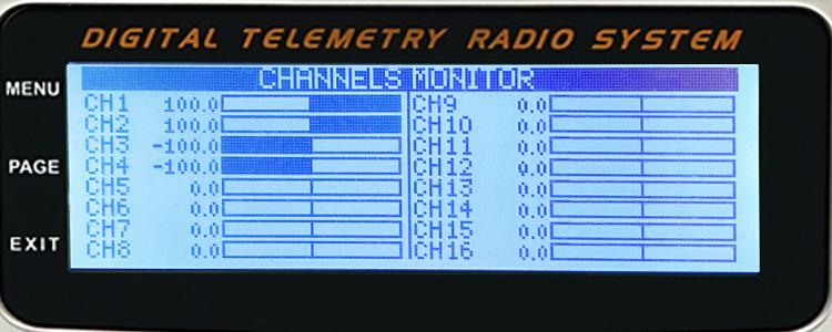
CH1 2000 µs (opentx +100), CH2 2000 µs (opentx +100)
CH3 1000 µs (opentx -100), CH4 1000 µs (opentx -100)
Servo Phase
Servo Phase Test
Please complete the attitude calibration first. After the attitude calibration is completed, you can test the servo phase. Otherwise, the control surface may swing abnormally.
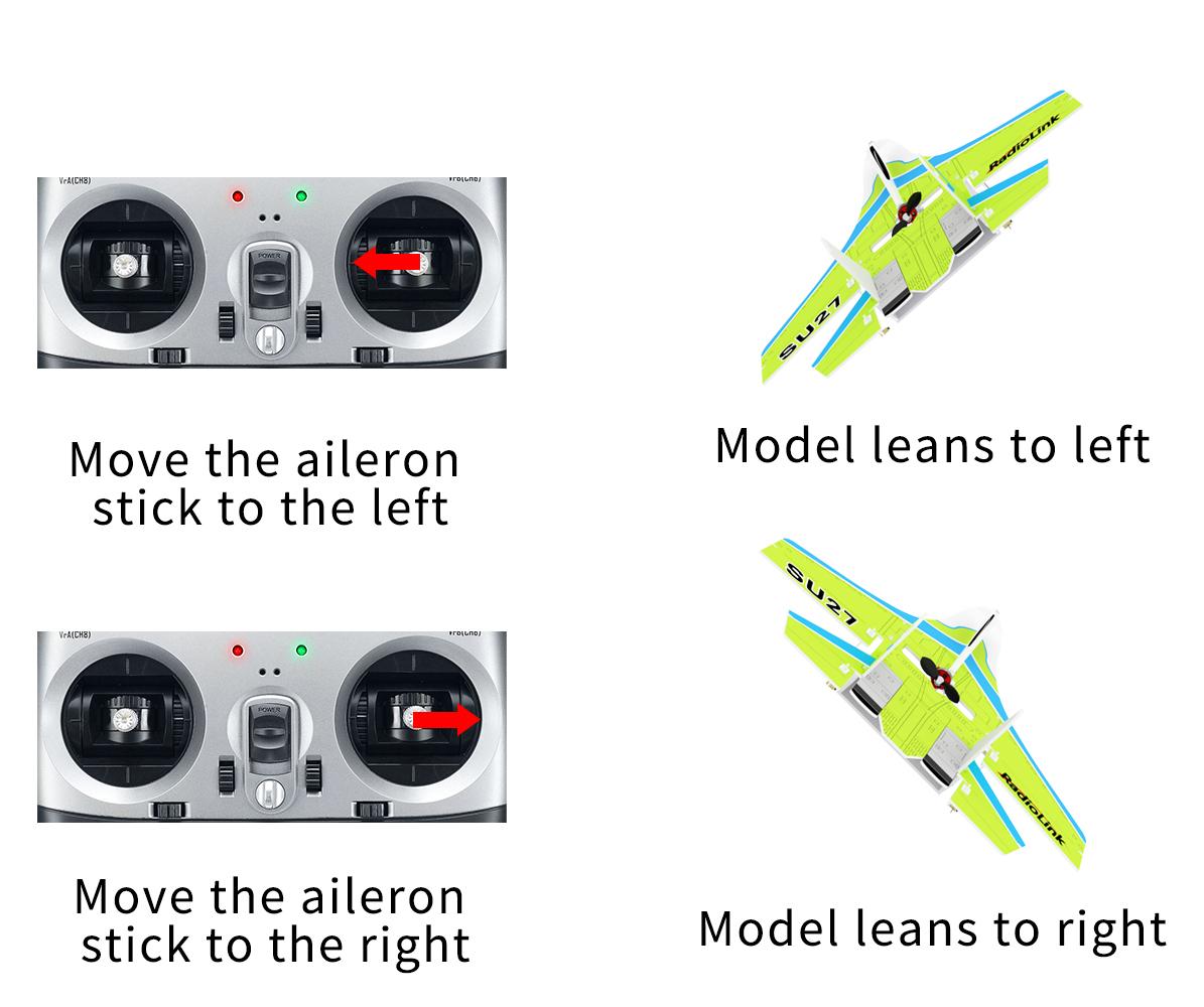
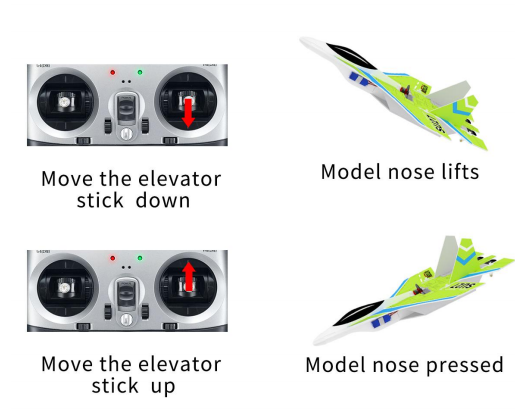
Switch to Manual mode. Check whether the movement of the joysticks matches that of the corresponding control surface. Take Mode 2 for transmitter as an example.
Servo Phase Adjustment
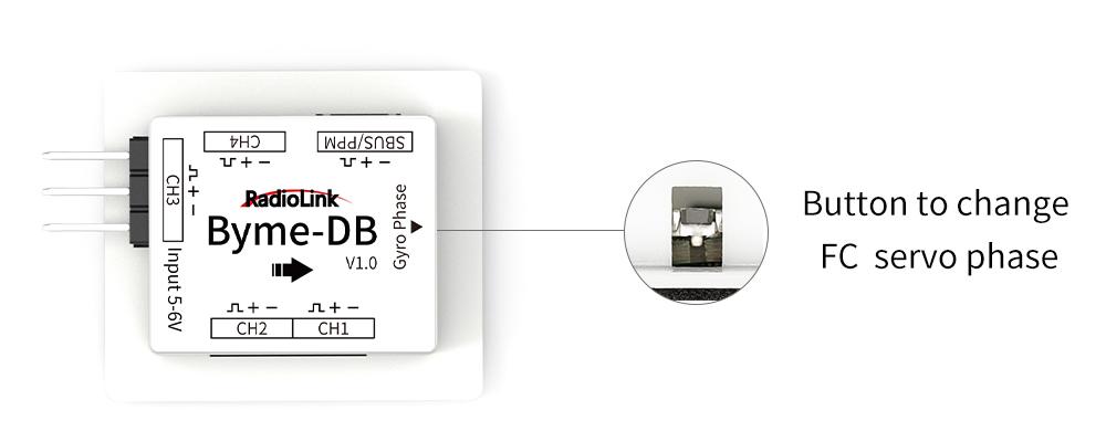
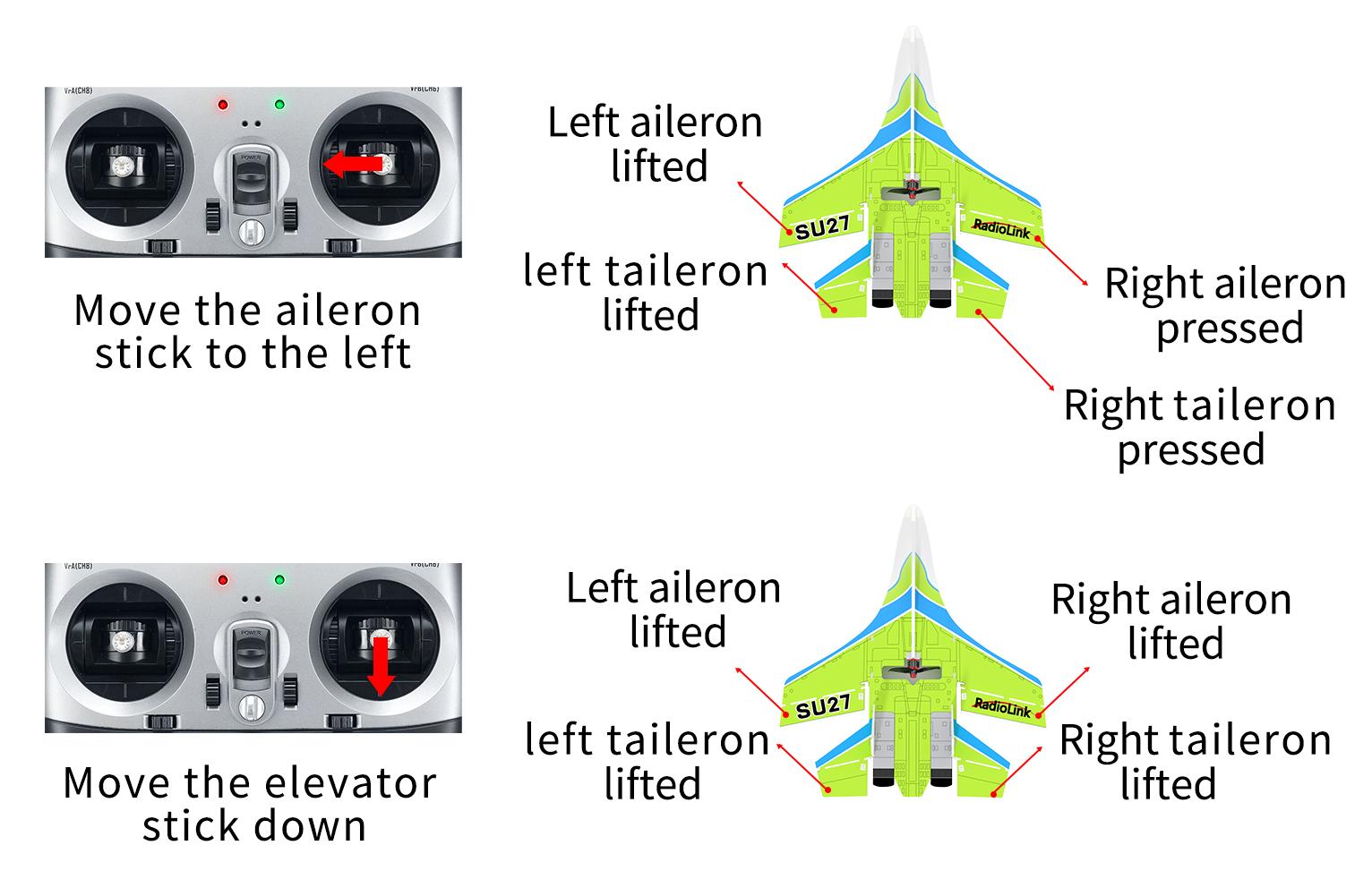
When the movement direction of the ailerons is inconsistent with the joystick movement, please adjust the servo phase by pressing the buttons on the front of the Byme-DB.
Servo phase adjustment methods:
Servo phase test result | Reason | Solution | LED |
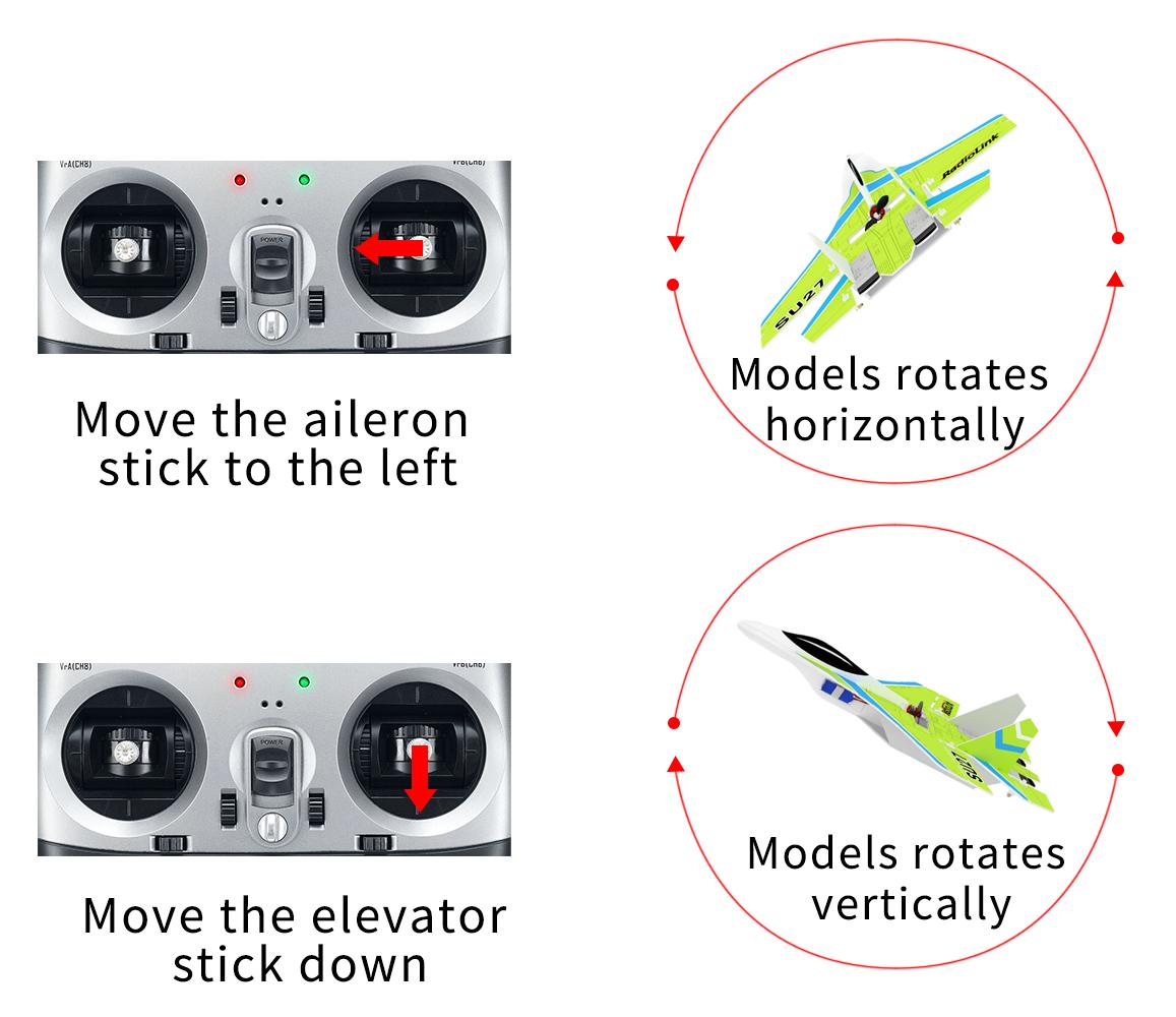
Move the aileron stick to the left, the movement direction of the ailerons and tailerons is reversed | Aileron mix control reversed | Short press the button once | Green LED of CH1 on/off |
Move the elevator stick down, the movement direction of the ailerons and tailerons is reversed | Elevator mix control reversed | Short press the button twice | Green LED of CH2 on/off |
Move the rudder joystick, the movement direction of rudder servo is reversed | Channel 4 reversed | Short press the button four times | Green LED of CH4 on/off |
Note:
Green LED of CH3 is always on.
Neither the always-on nor off green LED means reversed phase. Only toggle the joysticks can check if the corresponding servo phases are reversed. If the servo phase of the flight controller is reversed, adjust the servo phase by pressing the buttons on the flight controller. No need to adjust it in the transmitter.
Three Flight Modes
Flight modes can be set channel 5 (CH5) in the transmitter with 3 modes: Stabilize Mode, Gyro Mode and Manual Mode. Here is the introduction of the three flight modes. Take Mode 2 for transmitter as examples.
Stabilize Mode
Stabilize Mode with flight controller balancing, is suitable for beginners to practice level flight.
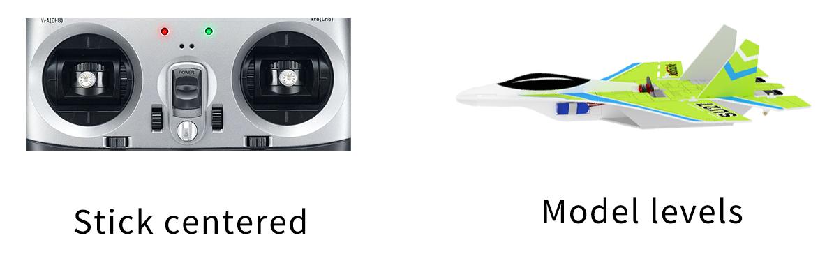
The model attitude (inclination angles) is controlled by joysticks. When the joystick is back to central point, the aircraft will level. The max inclination angle is 70° for rolling while that for pitching is 45°.
Gyro Mode
The joystick control the rotation (angle speed) of the aircraft. The integrated three-axis gyro assists to increase the stability.
(Gyro mode is the advanced flight mode. The aircraft won't level even the joystick is back to central point.)
Manual Mode
No assistance from flight controller algorithm or gyro, all flight movements are realized manually, which requires the most advanced skills. In Manual mode, it is normal that there is no movement of the control surface without any operation on the transmitter because there is no gyroscope involved in stabilize mode.
Gyro Sensitivity
There is certain stability margin for the PID control of Byme-DB. For aircraft or models of different sizes, if the gyro correction is insufficient or the gyro correction is too strong, pilots can try adjusting the rudder angle to adjust the gyro sensitivity.