
Specifications
Dimension | Dimension | 30.5*30.5mm(1.2″*1.2″) |
Weight | 9.5g | |
Hardware | Processor | STM32F722RET6 |
Sensor | Gyro | ICM42688 |
Barometer | BMP280/DPS310 | |
Blackbox | 128MB, record and store flight logs | |
OSD Module | AT7456E | |
Connector | Channel Output | M1 - M8 |
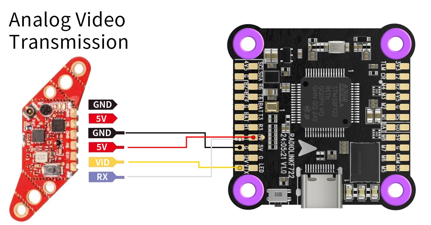
Video Transmission | transmission plug-and-play | |
Transmission | transmission plug-and-play | |
Soldering Pads | Support | |
Battery Scale | 110 | |
UART Port | 5 | |
ESC Features | Support | |
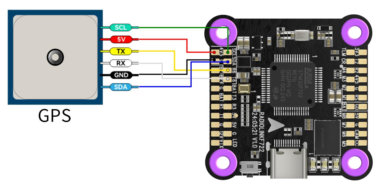
I2C | Support | |
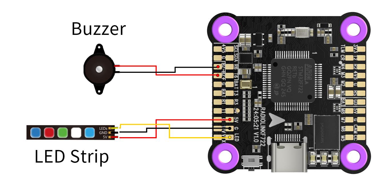
LED Strip | Support, with LED strip soldering pads | |
Buzzer | Support, with buzzer soldering pads | |
RSSI Output | Support, with RSSI soldering pads | |
Firmware Type | Betaflight | |
Firmware Name | RADIOLINKF722 | |
USB Port | 1 (Type-C) | |
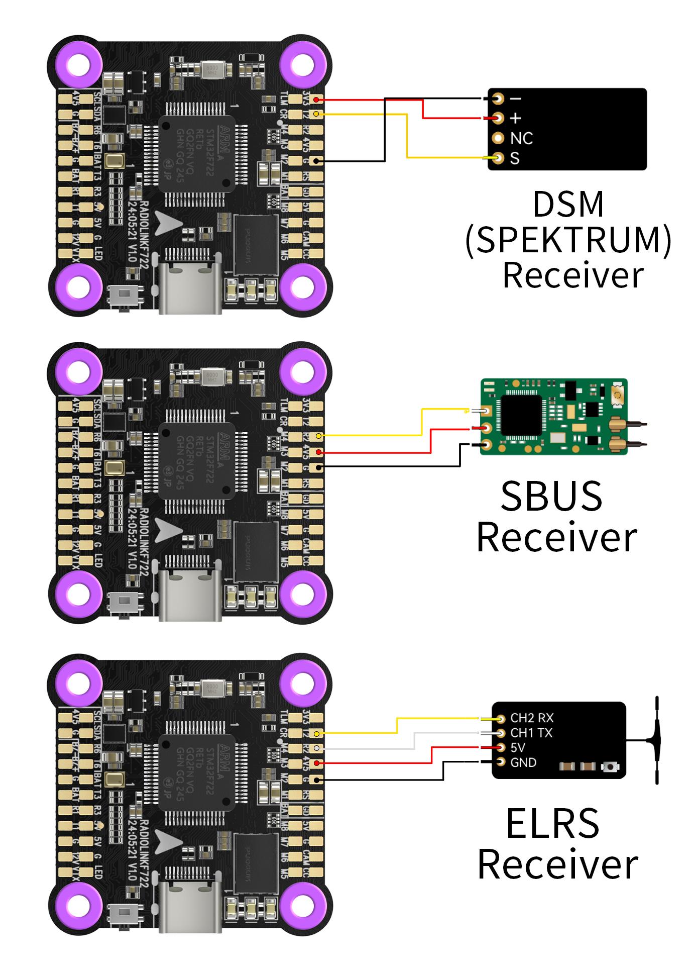
RC In Signal Input | SBUS/CRSF | |
OSD Telemetry | Support, OSD Module Integrated | |
ESC Protocol | PWM, two-way DShot, and OneShot Protocol | |
Input Voltage | 3-6S | |
BEC | 5V/3A; 12V/3A | |
12V BEC Switch | Support (USER1) | |
Adaptable Models | 2-8 axis multi-rotor including X8 models, Airplane, A-tail Quad, Bicopter, Custom Airplane, Custom Tricopter, Dualcopter, Flying-wing, Gimbal, Helicopter120, HEL+, HEX H, HEX X, OCTO FLAT+, OCTO FLAT X, OCTO X8, OCTO X8+, PPM to Servo, Quad+, Quad X, Quad X 1234, Singlecopter, Tricopter, V-tail Quad, Y4, Y6 | |
Operating Temperature | -30~85° |
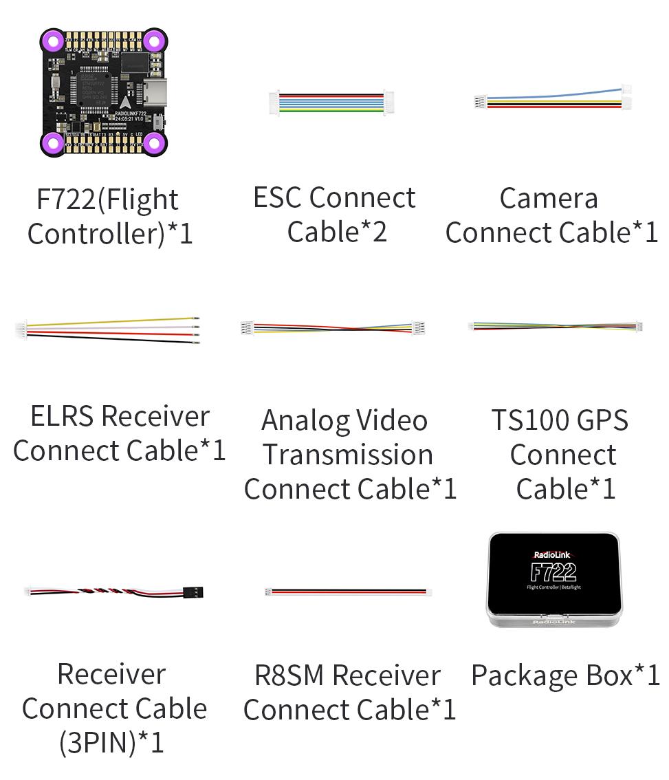
Package
LED Indicator

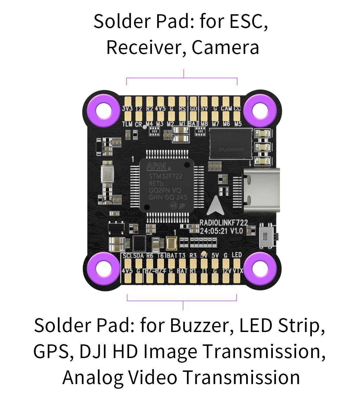
Soldering Pad Definition
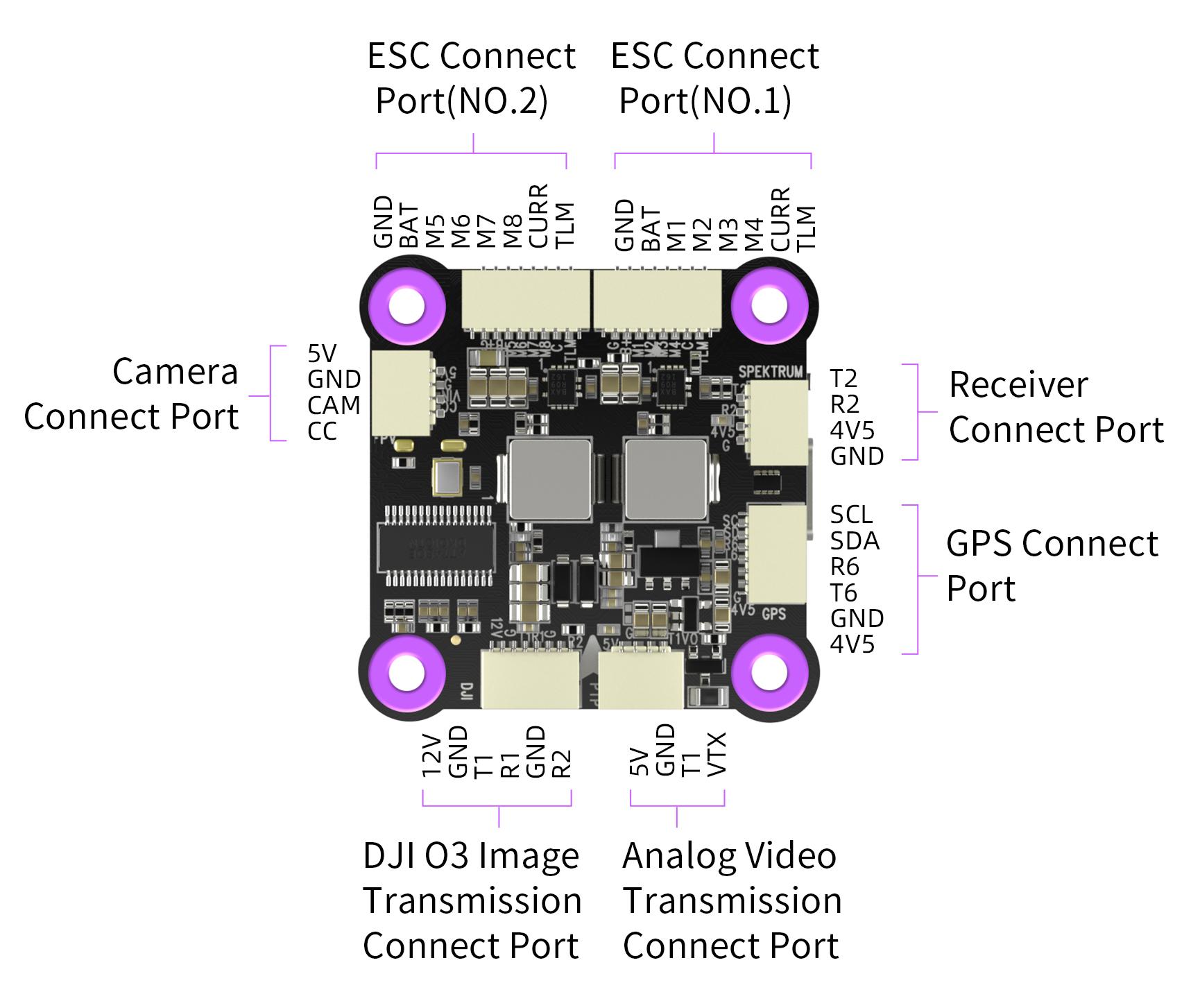
Socket Interface Definition
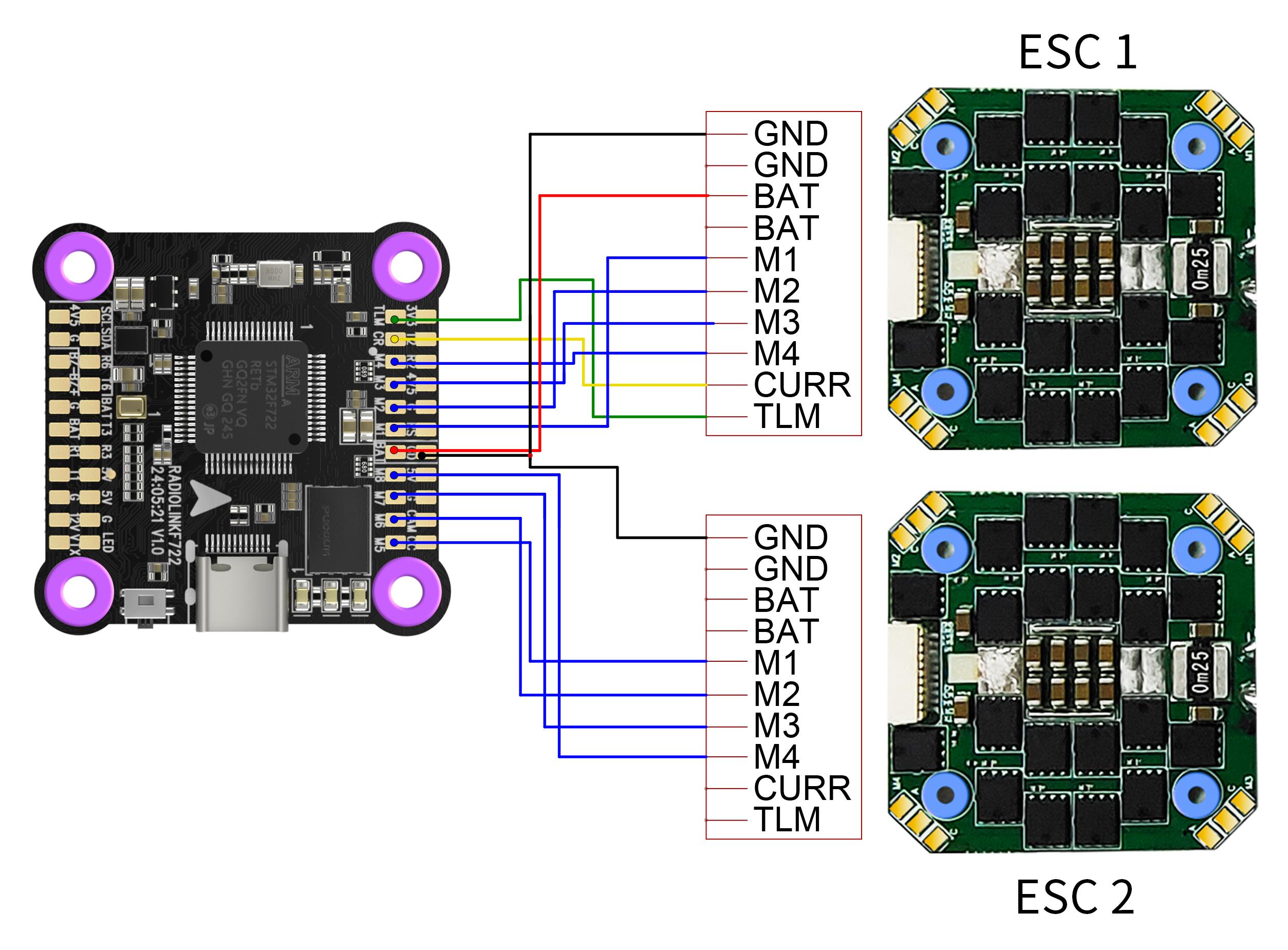
FC & ESC Connection
Method 1: All connectors
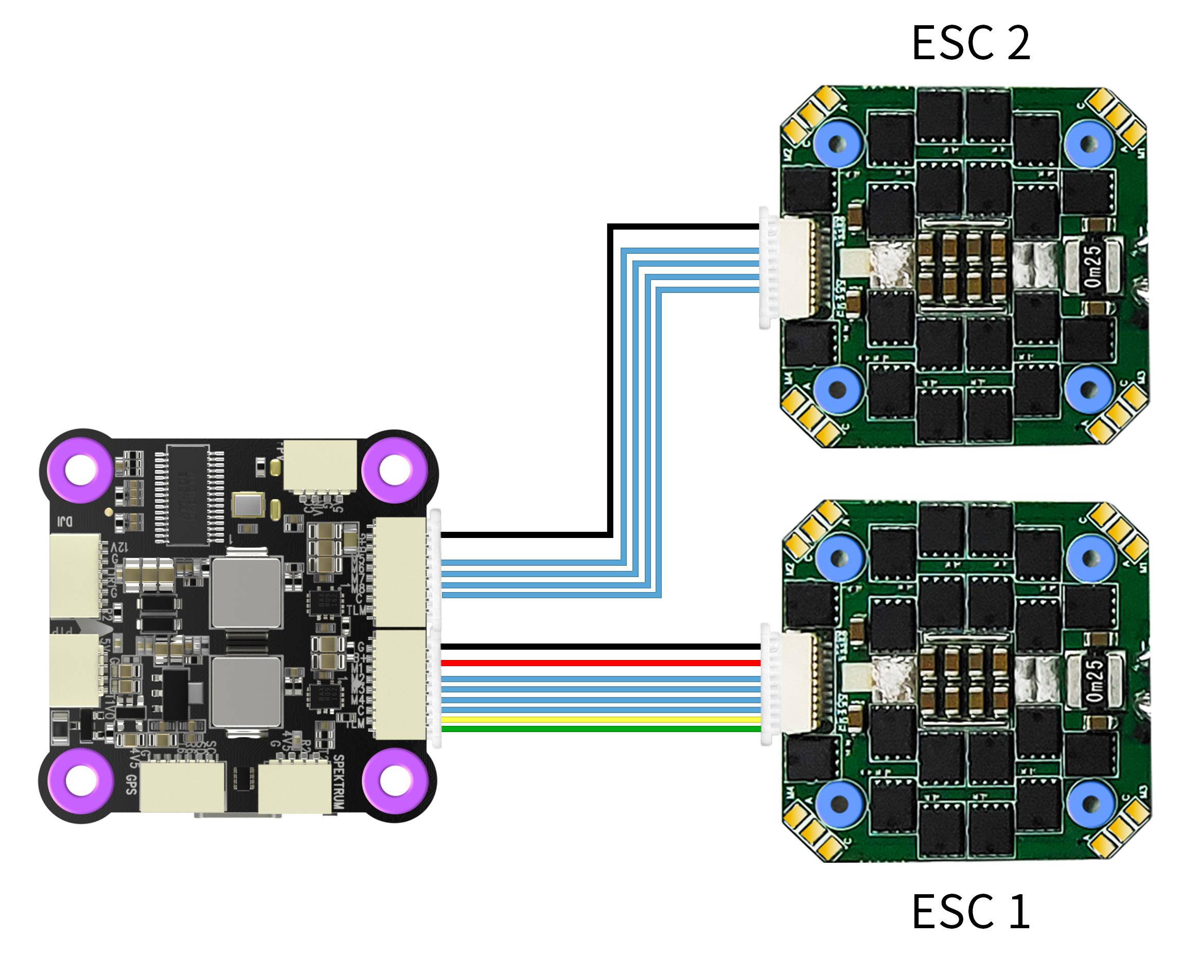
Note: When two ESCs are connected in this method, please disconnect the BAT, CURR, TLM cables for one of the ESC.
Method 2: Direct Soldering
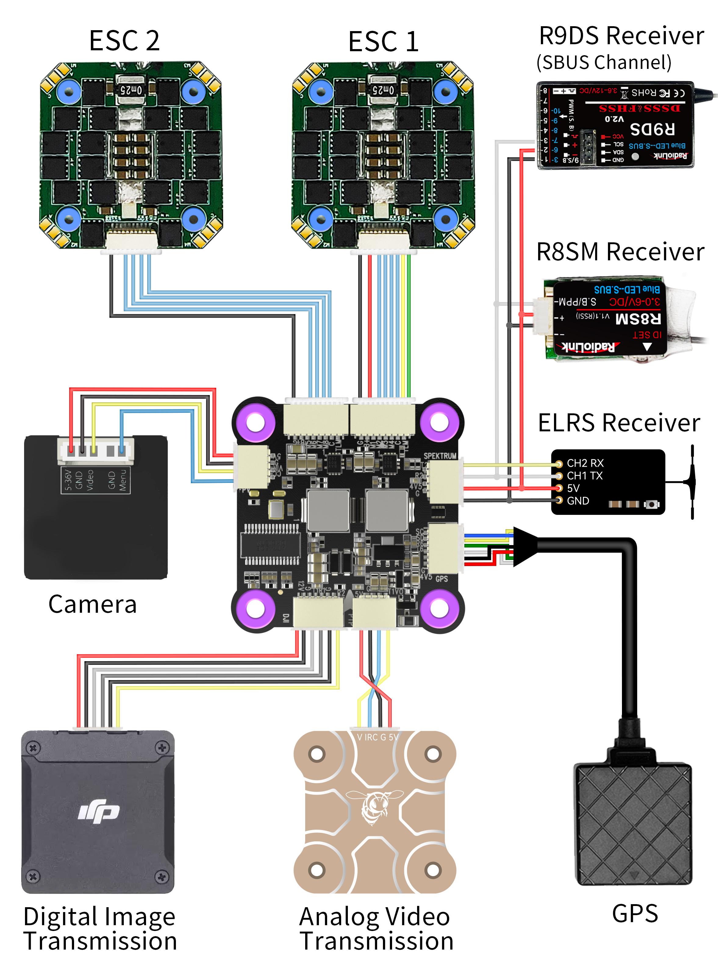
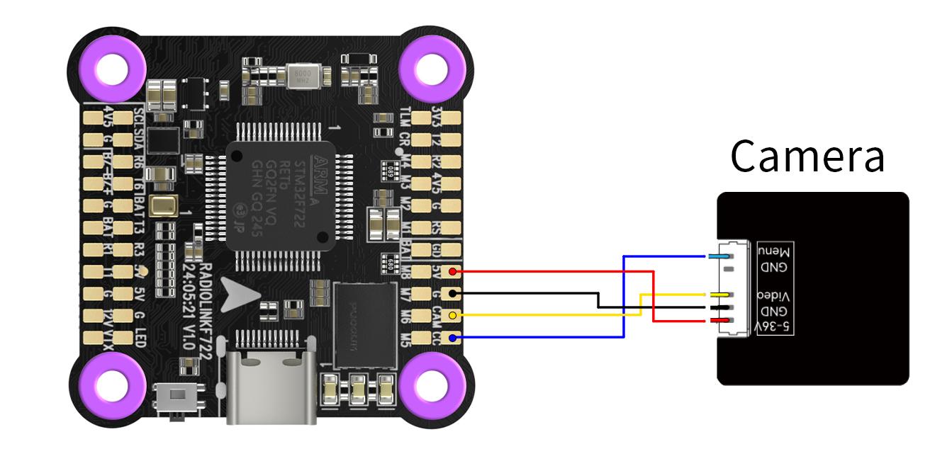
FC's Peripheral Connection
Method 1: All connectors
Method 2: Direct Soldering
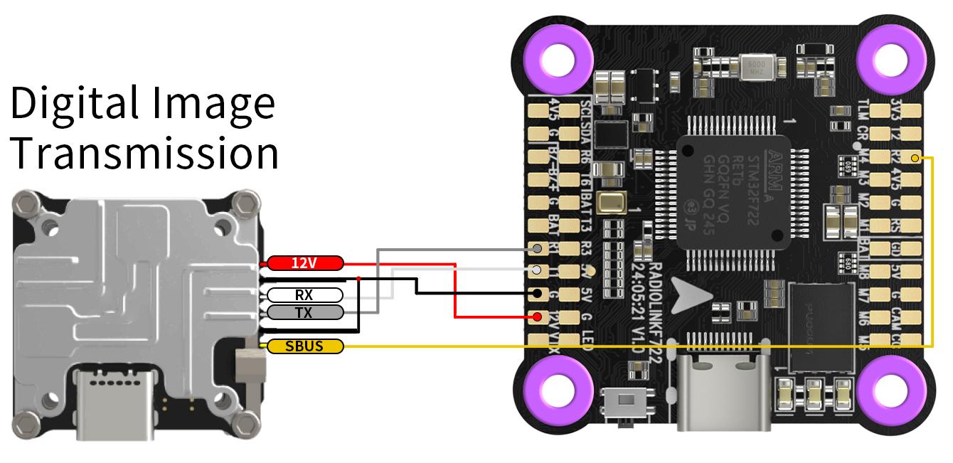
Note: when connecting DJI image transmission, the SBUS pin of DJI will occupy the R2 pin of F722. If DJI SBUS signal remote control is used, please disconnect the device on the R2 and T2 solder pad or on the receiver socket. If R2 and T2 solder pad or receiver socket are occupied to connect other receivers, please disconnect the DJI SBUS connection.
FC Firmware Update
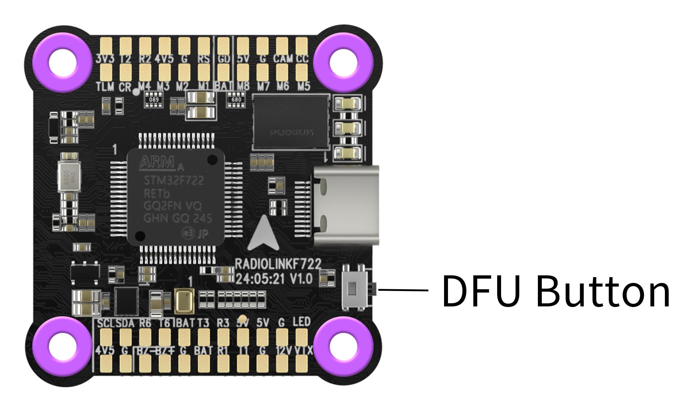
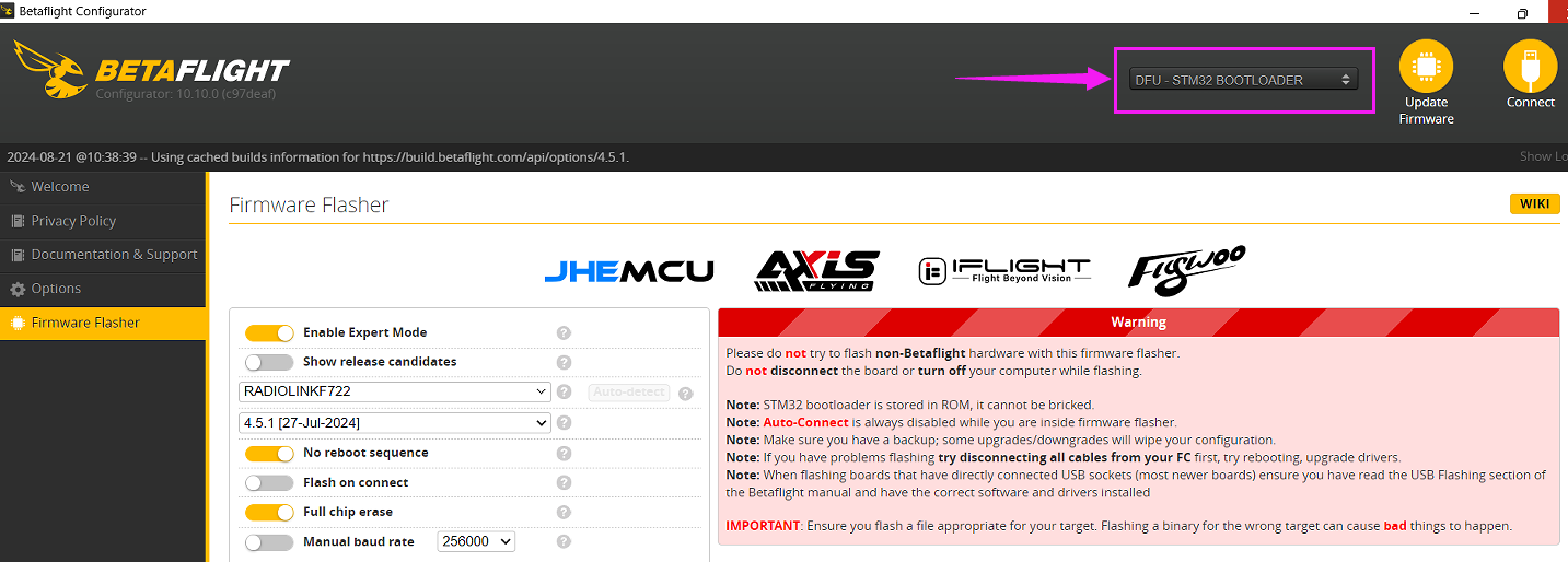
Long-press the DFU button. At the same time, connect F722 to the computer with a USB cable. Betaflight Configurator will display the DFU mode (See picture below);
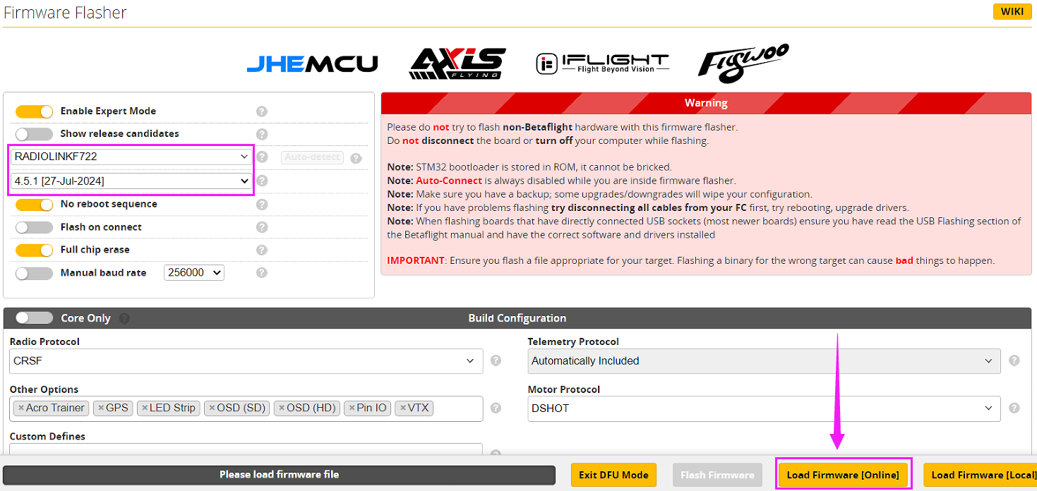
Select RADIOLINKF722 and 4.5.1 firmware in Betaflight Configurator. Then click “Load Firmware [Online]”;
After the firmware is loaded, click“Flash firmware”;

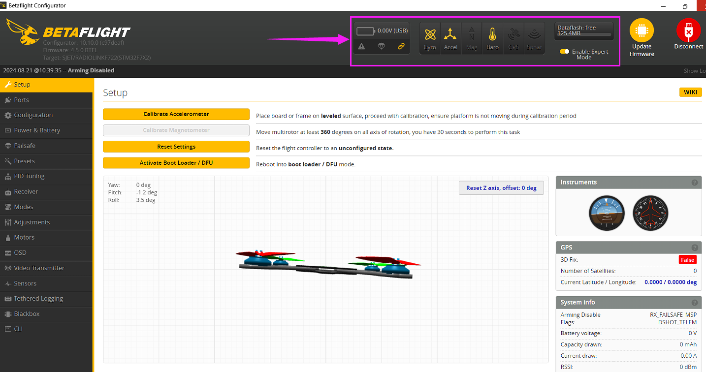
After the firmware is flashed, connect it to Betaflight Configurator again. The icon of gyroscope, accelerometer, barometer and DataFlash will be displayed.
If the above communication cannot solve your problem, you can also send emails to our technical support: after_service@radiolink.com.cn
Thank you again for choosing the RadioLink product.