
R16SM Introduction
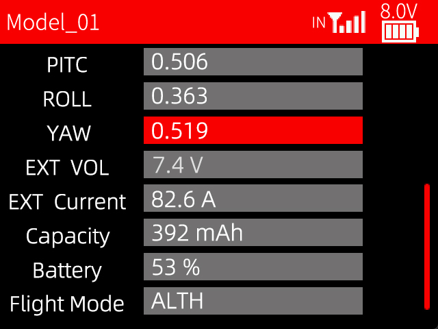
RadioLink R16SM is a mini 16-channel receiver with 3000 meters control distance. R16SM has a built-in data transmission function, allowing for the transmission of rich information without the need for external sensors. In addition to real-time transmission of the RSSI value and model battery voltage, the OSD information such as latitude, longitude, speed, heading, the number of GPS satellites received, distance, PITC, ROLL, YAW, battery voltage, current, capacity, flight mode will be displayed on the transmitter screen when R16SM is connected to a flight controller and GPS, and in CRSF working mode.
Receiver Protocol Selection
If R16SM is used together with T16D/T12D, please select receiver protocol in the transmitter. Enter Transmitter Setting--RF SETTING (If RC8X is used, please enter Basic menu--Receiver setting to select the protocol). Please select internal module, and then select the protocol (As shown on the right). R16SM supports FHSS V1, FHSS V2 and FHSS V2.1 protocol. It is recommended to select FHSS V2.1 protocol. For the differences of the protocols, please refer to the table below:

Protocol | PWM Output Resolution | Servo Speed | Channel Number | Compatible Receiver |
FHSS V1 | 2048 | 14ms | 8 | All receivers compatible with T16D/T12D |
FHSS V2 | 4096 | 3ms/4ms/14ms available | 8 | R16SM, R16F, R12F, R8FGH, R8FG V2.1, R4FGM V2.1, and R8FG and R4FGM receivers with a factory date of 2023/4/26 or later |
FHSS V2.1 | 4096 | 3ms/4ms/14ms available | 16 | R16SM, R16F, R12F |
If digital servo is used, you can select 3ms or 4ms servo speed. | ||||
Binding
Each receiver has an individual ID code and must bind with transmitter before using. When the binding is done, the ID code will be stored in the transmitter and there is no need to rebind. Therefore, when a new R16SM is purchased, binding needs to be done in order to work with transmitter.
Here are the binding steps of R16SM:
- If T16D/T12D/RC8X transmitter is used, please select the receiver protocol on the transmitter. (Please refer to Chapter 2. Receiver Protocol Selection) Note: If you are using a transmitter other than 16D/T12D/RC8X, such as RC6GS/RC4GS/T8S/T8FB, etc, go to step 2 directly.
- Place the transmitter and R16SM receiver more than 30 centimeters apart.
- Power on the transmitter and R16SM.
- Press the binding button on the side of the receiver for more than 1s and the LED indicator of the receiver will flash, meaning the binding process has begun.
- When the LED indicator stops flashing, binding is complete. If the LED indicator keeps flashing slowly, binding fails, Please rebind them by following the above steps.
When the transmitter and receiver are powered on, the LED indicator of R16SM flashes slowly means there is no binding or the receiver loses signal during flight.
Working Modes
R16SM supports two working modes. One is uninverted SBUS signal output, and the other one is CRSF signal output. Blue LED indicates CRSF signal output, while red LED indicates uninverted SBUS signal output. Short press the binding button once to switch the working mode.
Real-time Built-In Telemetry and the Connection to the Flight Controller
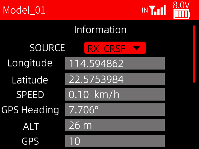
R16SM supports different telemetry information when in SBUS or CRSF signal output. In CRSF signal output, R16SM supports the telemetry of signal strength, RSSI value, power battery voltage, longitude and latitude, distance, number of satellites etc (As shown below); while in SBUS signal output, R16SM only supports the telemetry of longitude, latitude and power battery voltage, so it is recommended to use CRSF signal working mode. Note: The CRSF protocol does not support the telemetry of the receiver voltage, so R16SM does not support receiver voltage telemetry.
Here are the connection diagram and the setting methods for CRSF and SBUS signal working modes when different flight controllers are used.
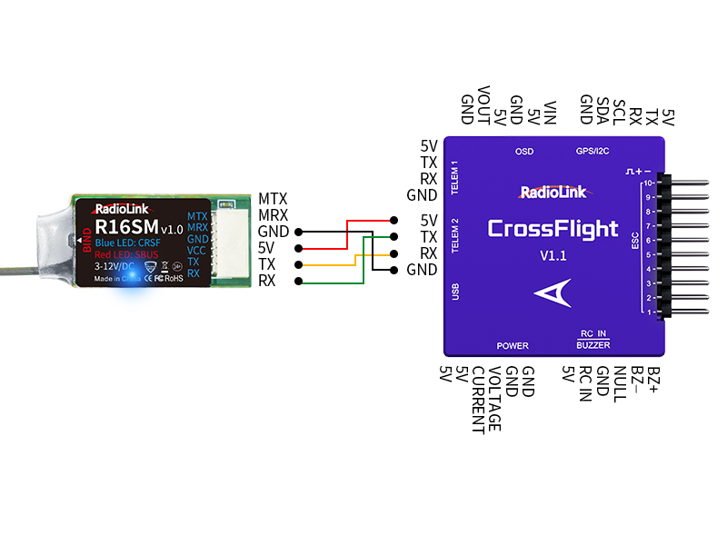
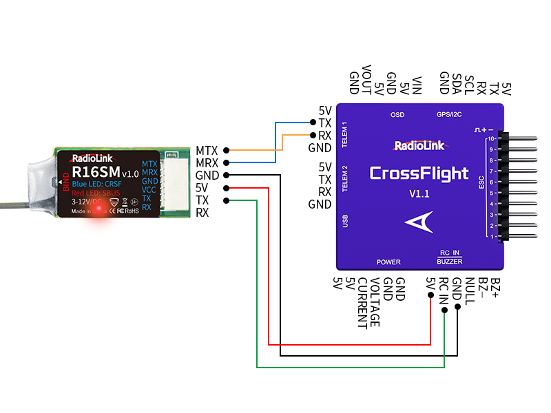
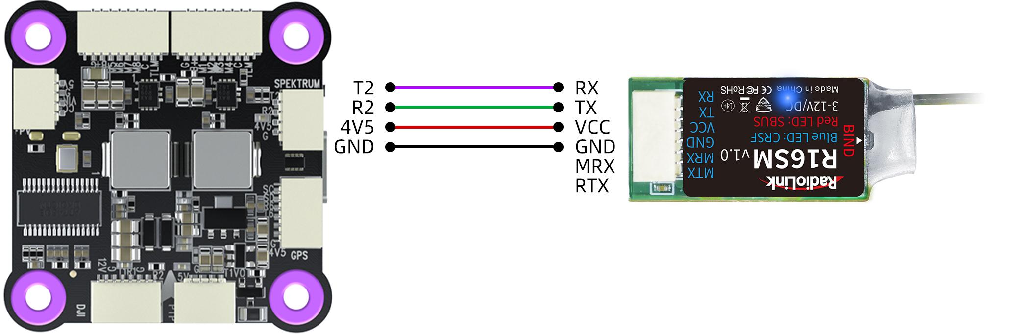
When RadioLink CrossFlight is used with R16SM
CRSF signal working mode, with blue LED.
The TX of R16SM is connected to the TELEM2 RX, and RX is connected to the TELEM2 TX, as shown below:
Please set the following 6 parameters in Mission Planner:
Set SERIAL2_BAUD to 115
Set SERIAL2_OPTIONS to 0
Set SERIAL2_PROTOCOL to 23
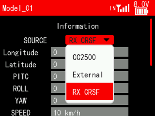
And please select RX CRSF on the telemetry information menu of T16D/T12D:
Uninverted SBUS signal working mode, with red LED.
The MTX of R16SM is connected to the TELEM1 RX, the MRX is connected to the TELEM1 TX (If MTX and MRX of R16SM are not connected to the flight controller, there will be no telemetry information), and the TX of R16SM is connected to the RC IN of the flight controller, as shown below:
Please set the following 6 parameters in Mission Planner:
Set SERIAL1_BAUD to 57
Set SERIAL1_OPTIONS to 0
Set SERIAL1_PROTOCOL to 2
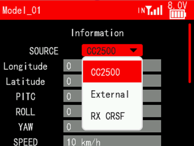
And please select CC2500 on the telemetry information menu of T16D/T12D:
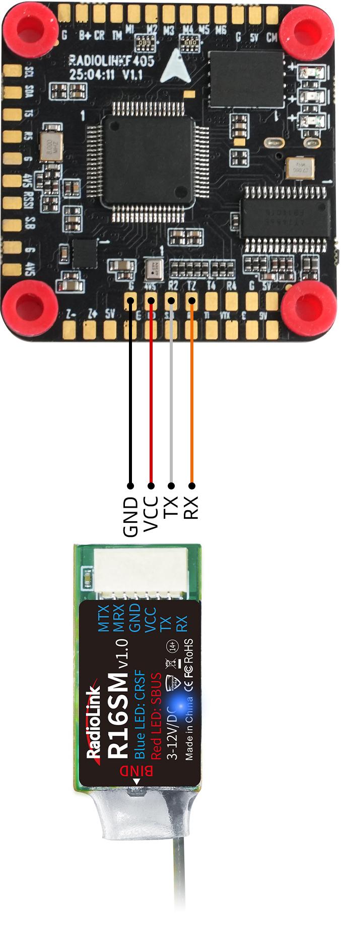
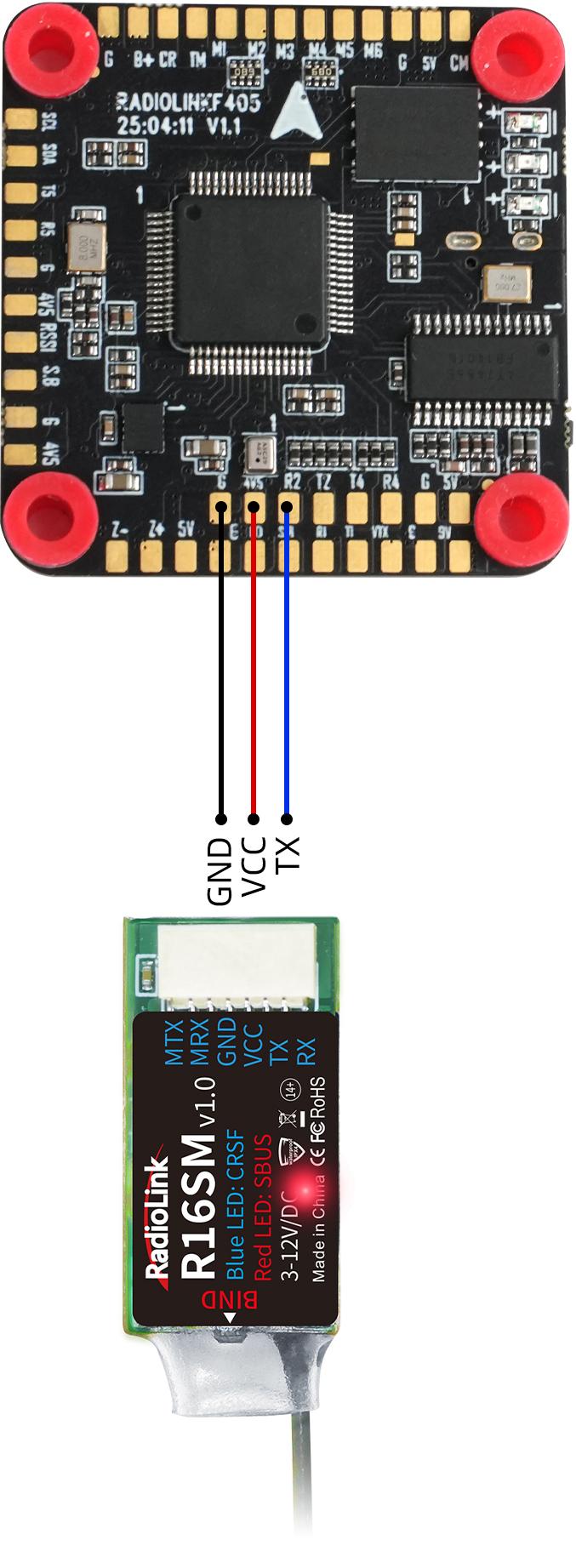
When RadioLink F405 is used with R16SM
CRSF signal working mode, with blue LED. The connection is as shown below:
Please set SERIAL1_PROTOCOL to 2 in Mission Planner. (Depend on the used serial port )
And please select RX CRSF on the telemetry information menu of T16D/T12D:
Uninverted SBUS signal working mode, with red LED. The connection is as shown below:
Please set SERIAL1_PROTOCOL to 2 in Mission Planner. (Depend on the used serial port )
And please select CC2500 on the telemetry information menu of T16D/T12D:
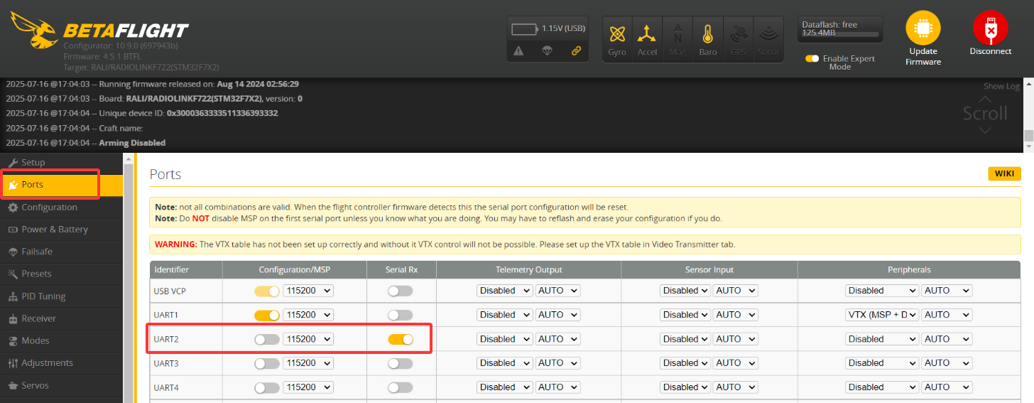
When RadioLink F722 is used with R16SM
R16SM can only work with F722 by using CRSF signal, with blue LED. The connection is as shown below:
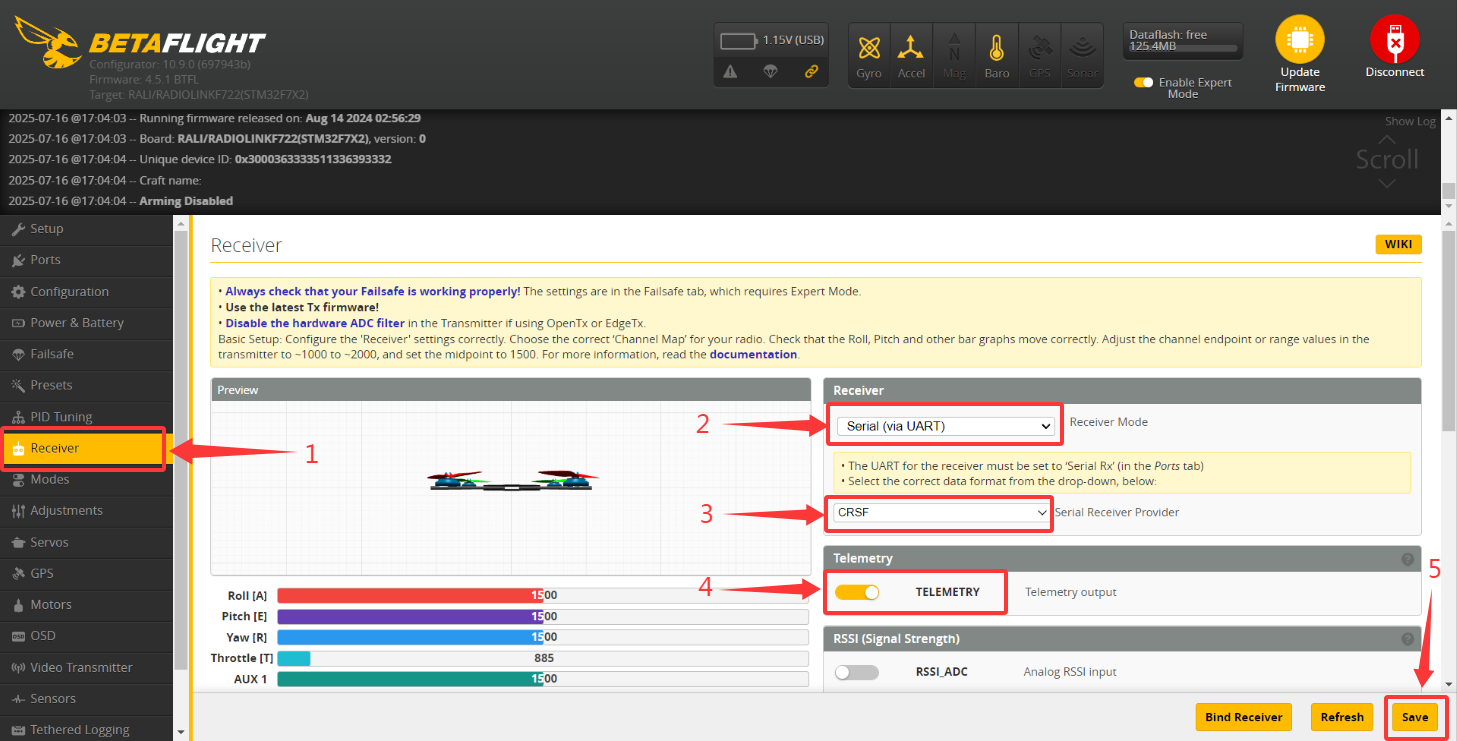
Please set parameters in Betaflight/INAV configurator. Here are the setting steps. Click Ports and open the used serial port. Click Receiver. Select Serial (via UART)--Select CRSF--Turn on Telemetry--Click Save. The steps are as shown below:
And please select RX CRSF on the telemetry information menu of T16D/T12D:
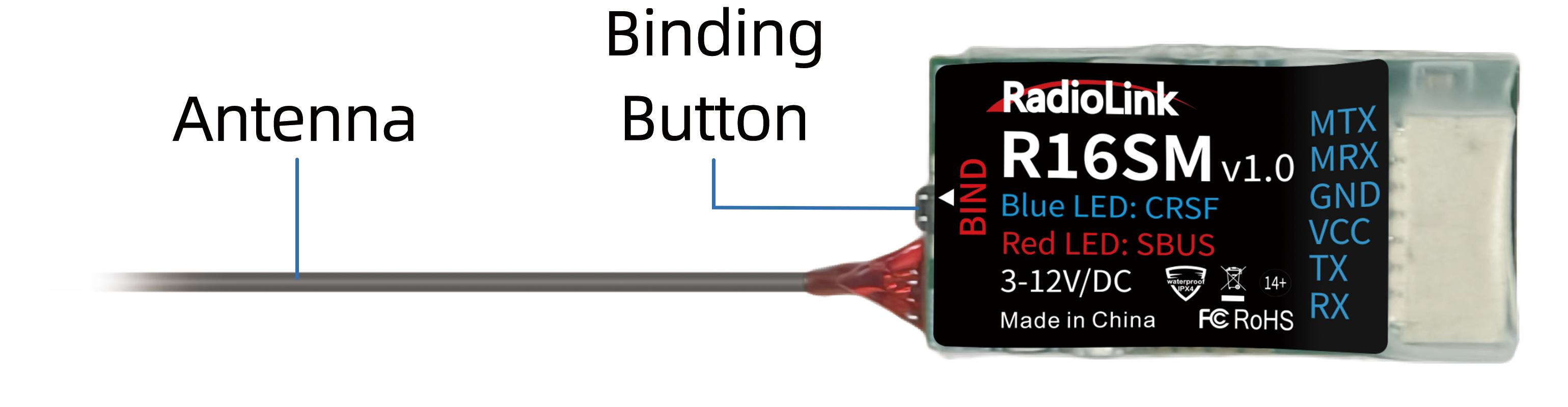
Note of Antenna Installation
It is very important to correctly install the receiver antenna on the model, because incorrect antenna installation will affect the signal.
- The following requirements should be noted when installing the receiver antenna:
- The receiver antenna cannot be folded.
- The antenna should not be close to metal objects, because reflection from the metal will cause the signal to deteriorate sharply.
- Keep antennas as straight as possible, or the effective control range will reduce.
- Big models may contain metal parts that influence signal emission. In this case. antennas should be positioned at both sides of the model to ensure the best signal status in all circumstances.
- Antennas should be kept away from metal conductor and carbon fiber at least half inch away and no over bending.
- Keep antennas away from motor, ESC or other possible interference sources.
- Sponge or foam material is advised to use to prevent vibration when installing receiver.
- Receiver contains some electronic components of high-precision. Be careful to avoid strong vibration and high temperature.
Special vibration-proof material for R/C like foam or rubber cloth is used to pack to protect receiver. Keeping the receiver in a well sealed plastic bag can avoid humidity and dust, which would possibly make the receiver out of control.
Refer to the following link to view the guide on antenna installation:
https://www.radiolink.com/newsinfo/886600.html
RSSI Testing
If the control distance is short, please refer to this instruction to test the RSSI between the transmitter and receiver. This instruction will introduce the test procedure of the transmitter RSSI value and the solution to the abnormal RSSI value.
1.Turn on the transmitter and power on the receiver at the same time, and then the transmitter and receiver will be connected (if not connected, you need to bind again). The signal tower appears on the transmitter interface, indicating that the binding is successful. The value of RSSI will appears on the home page (As shown on the right), and the RSSI value will keep changing according to the distance between the transmitter and the receiver.
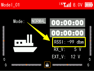
2.Make the receiver antenna and transmitter antenna parallel. Keep transmitter apart from receiver about 60 centimeters and both antennas straight. It is normal that RSSI value is within the range of 0 to -30dBm. The closer the value is to 0, the stronger the signal is.
Abnormal signal strength solution:
Check whether the antennas of the receiver and transmitter are damaged. Most signal strength degradation is caused by antenna damage. If it is damaged, the antenna needs to be replaced. If there is no damage, you can test the transmitter and receiver for malfunctions by replacing the receiver. If still cannot solve the problem, email to after_service@radiolink.com.cn to get support.
R16SM Specifications
Model name: R16SM
Dimension: 22*11.3*6mm(0.87"*0.45"*0.24")
Weight: 1.5g (0.05oz)
Antenna Length: 90mm (3.54”)
Channel: 16 channels
Operating Voltage: 3-12V
Operating Current: 45-70mA@5V
Signal Output: SBUS, CRSF
Output Frequency: 2.4GHz ISM band(2400MHz~2483.5MHz)
Spread Spectrum: FHSS 67 channels pseudo-random frequency hopping
Section Precision: 4096, 0.25us per section
Adaptable Models: Helicopter, Fixed-wing, Glider, Multicopter, Car, Boat, Robot (must work with a flight controller)
Control Distance: 3000 meters in the air (Maximum range is tested in an unobstructed area free of interference)
Telemetry: R16SM has built-in data transmission functions. When connected to the flight control and at the CRSF signal, they can send back information such as latitude and longitude, distance, number of satellites, heading, and other information in real-time.
EXT Battery Input: Depends on the flight controller input voltage
Response Latency: When bound to T16D/T12D/RC8X, 3ms, 4ms, and 14ms can be selected. When bound to other transmitters, it defaults to 14ms.
Operating Temperature: -30° to 85°C
Compatible transmitter: T16D, T12D, T8FB, T8S, RC8X, RC6GS V3, RC4GS V3, RC6GS V2, RC4GS V2, RC6GS, RC4GS
Thank you again for choosing RadioLink product.