
R7FG Introduction
1 、Compatible transmitters
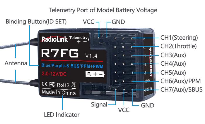
RadioLink R7FG 2.4G 7-channel receiver, splash-proof, with integrated gyro for professional car drifting and high voltage servo supported is compatible with RadioLink RC6GS V3/RC6GS V2/RC6GS/ RC4GS V3/RC4GS V2/RC4GS/ RC3S/RC4G/T8FB/T8S.
2、 Binding
Each receiver has an individual ID code and must bind with transmitter before using. When the binding is done, the ID code will be stored in the transmitter and there’s no need to rebind. Therefore, when a new R7FG is purchased, binding needs to be done in order to work with transmitter.
Binding steps:
- Put the receiver and the transmitter close to each other (about 50cm).
- Power on the transmitter and R7FG will bind to the closest transmitter automatically.
- Press the ID SET on the receiver’s side for more than 1s and the GREEN indicator will flash, meaning the binding process has begun.
- When the GREEN indicator stops flashing, binding is complete.
- Test the model servo to make sure it can be operated by the transmitter.
Note:
- The binding between your R7FG and RC6GS V3 is already complete by default. Just need to make sure there is the solid light of R7FG and the signal tower in the transmitter.
- NO gyro by default as factory setting. Since integrated gyro in R7FG will self-check, it is very imporant to remain R7FG still when powering it on. GREEN LED (always on) indicates normal working mode while PURPLE and RED LEDs (always on) indicate gyro working mode. When RED is off means NO gyro. If binding is not successful, the green led will keep flashing to notify.
Telemetry
R7FG can return the real-time flight information such as RSSI, receiver voltage and model battery voltage.
In order to enjoy this function, please upgrade RC6GS(3-position switch version) with the firmware RC6GS_RadioLink_bin_1d15_V_6_1_2 downloaded via
https://www.radiolink.com/rc6gs_firmware
Or upgrade RC4GS(produced after 2018-01-01) with the firmware RC4GS_RX_RadioLink_bin_2f50_V_6_0_1 downloaded via
https://www.radiolink.com/rc4gs_firmware
If you are using RC6GS V3, RC6GS V2, RC4GS V3 or RC4GS V2, the default firmware supports telemetry function.
1 、Telemetry of Signal and RSSI
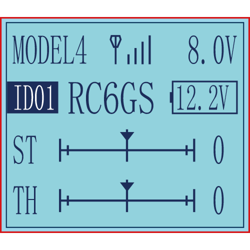
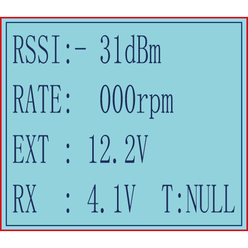
Power on the transmitter and the receiver and complete the binding, signal will be displayed on the homepage of transmitter. Short press EXIT twice and enter the interface with returned information including RSSI value.
Warning can be set with a certain low RSSI value after testing by changing distance:
Press EXIT and ENTER simultaneously to enter MENU=>press Inc(+) to highlight “19. ALARM =>Press ENTER to (dis)activate the warning and set the RSSI warning value.
Note: R7FG is the receiver with dual antenna. When the distance between the transmitter and the R7FG is 50 centimeters, it is normal that RSSI value is within the range of 0 to -30dBm. The closer the value is to 0, the stronger the signal is. The range of RSSI value of RadioLink transmitters is from 0 to -99dBm. The larger the absolute value of the RSSI value is, the weaker the signal is. For example, the signal when the RSSI value is -90dBm is weaker than the signal when the RSSI value is -75dBm.
2 、Telemetry of model battery and receiver voltage
Besides the return of receiver voltage, model battery voltage (maximum up to 8S lithium battery) can also be returned in real time. Users can personalize the warning value of low model battery voltage depending on the actual needs.
Press EXIT and ENTER simultaneously to enter MENU=>press Inc(+) to highlight “19. ALARM =>Press ENTER to set the model battery voltage warning value.
Normally we set the warning value with the single cell voltage as 3.7V. For example, if it is 3S lithium battery used in the model car, the warning value should be set as (3.7V*3S=)11.1V.
Model battery voltage return can be easily achieved by connecting the male end of the battery wire to ESC while the female end to the battery and the wire with a JST head connects Telemetry (+-) port of R7FG/R8F as below pic shown. No extra module is needed.
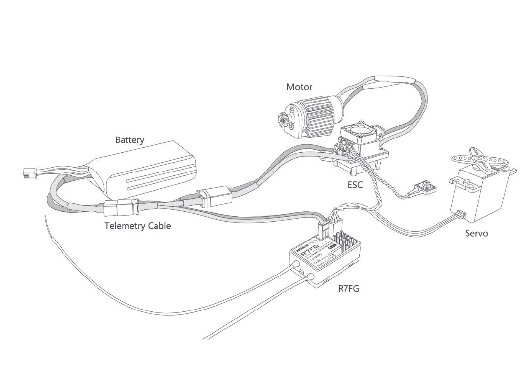
When connect with success, users can check the battery voltage on the main interface of the transmitter.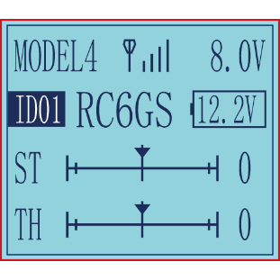
Subsidiary ID
Subsidiary ID function means designating a subsidiary ID among multiple binding receivers to realize the control and it can be realized by on the ID seed menu of RC6GS(3-way switch version with latest firmware V6.0.0) or RC4GS(Produced after 20180101 with the latest firmware V6.0.1). There are totally 10 independent subsidiary IDs can be stored in a transmitter.
For example, RC6GS has completed the binding with 10 different boats and the setup of respective parameters. Turn on the ID SEED function, select ID.1 boat and drive it to the central of water but it stops working unexpectedly. Then we can change to the ID.2 boat (or any other subsidiary ID boat preferred) and control it independently to rescue ID. 1 boat instead of controlling both boats at the same time, which makes the rescue more difficult. Unlike traditional binding mode, independent ID can easily realize.
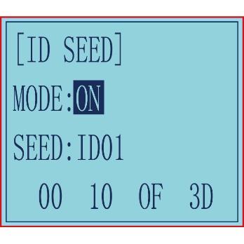
Press EXIT and ENTER simultaneously to enter MENU=>press Inc(+)/DEC(-)to highlight “22. ID SEED=>Press ENTER => Change the MODE from OFF to ON=> set the subsidiary ID number=> complete biding and parameters setting.
Once finished , the corresponding ID number will be displayed on the RC6GS main interface .
Then the other receivers can be bounded as the same way with the following numbers.
Working Modes
R7FG has four working modes:
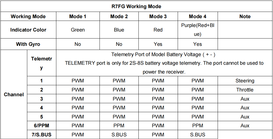
Mode 1: PWM output (factory setting by default, NO gyro)
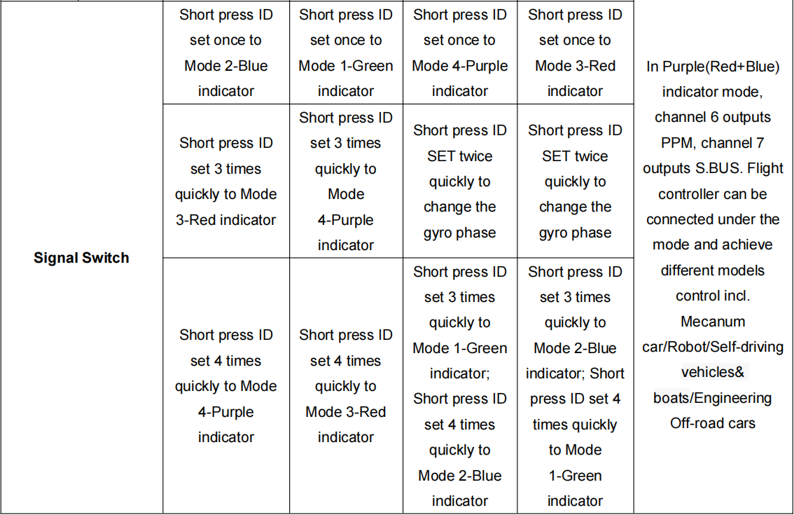
When the Green indicator is on, Channel 1 to Channel 7 output standard PWM. Short press ID SET once to change Mode 1 to Mode 2 and three times within 1 second to Mode 3.
Mode 2: PWM+PPM+SBUS output (NO gyro)
When the Blue indicator is on, Channel 1 to Channel 5 output standard PWM while Channel 6 outputs PPM and Channel 7 outputs SBUS. Short press ID SET once to change Mode 2 to Mode 1 and three times within 1 second to Mode 4.
Mode 3: PWM output + Gyro
When the Red indicator is on, Channel 1 to Channel 7 output standard PWM. Meanwhile, the Gyro function is also on, stabilizing the direction, keeping car from slipping and ensuring safer turning to preventing drifting from fast speed. Short press ID SET once to change Mode 3 to Mode 4 and three times within 1 second to Mode 1. Short press ID SET twice in 1 second to change the gyro phase.
Mode 4: PWM+PPM+SBUS output + Gyro
When both the Red and the Blue indicators are on (Purple), Channel 1 to Channel 5 output standard PWM while Channel 6 outputs PPM and Channel 7 outputs SBUS. Meanwhile, gyro function is also on, stabilizing the direction, keeping car from slipping and ensuring safer turning to preventing drifting from fast speed. Short press ID SET once to change Mode 4 to Mode 3 and three times within 1 second to Mode 2. Short press ID SET twice in 1 second to change the gyro phase.
Gyro Introduction
1、 Gyro Function
The R7FG integrated gyro for professional car drifting can be enabled and disabled. When it’s enabled, the turning stability can be maximized during competition. When there is false position, gyro function keeps the car straight forward and turn precisely.
2、 Gyro Enabled
Factory setting is gyro function OFF by default.
Short press ID SET three times with interval less than 1 second, the RED indicator flashes three times. Red LED on/off indicates the gyro function is on/off.
3、 Gyro Phase
When the gyro forward is enabled, try to turn the model car to check if the gyro is correcting the wheels. Normally, the wheels should turn right to correct when the car is turned left while the wheels should turn left to correct when the car is turned right. If the gyro phase is reversed, short press the binding button (ID SET) twice in 1 second in mode 3 and mode 4. The indicator flashes once means the gyro phase setting is complete.
4、 Transmitter Sensitivity Adjustment
Gyro sensitivity setting is CH3 by default (factory setting) and can be adjusted by the VR rotary switch. Percentage is displayed when sensitivity is adjusted while the bigger percentage means higher sensitivity. If the VR rotary switch/CH3 is set with other function, MODE can be changed to STD in GYRO setting of the menu to adjust gyro sensitivity with buttons Dec(-) and Inc(-).
R7FG Specifications
Frequency:2.4GHz ISM band(2400MHz~2483.5MHz)
Dimension: 35*22*13mm
Weight: 6g
Channel Qty::7 channels
Signal Output:PWM/PWM&PPM&SBUS
Model Application: Car/Boat/Fixed Wing/Glider/Multirotor
Encode: FHSS 67-channel pseudo random frequency hopping
Antenna Length:205mm(dual antennas)
Voltage Range:3-12V
Channel Resolution: 4096
Operating Current: 30mA ( Depending on power supply)
Backhaul: Signal/RSSI/Model Battery Voltage
Control Distance: 600 meters on the ground
Compatible transmitter:RC6GS V3/RC4GS V3/RC6GS V2/RC4GS V2/RC6GS (3-position switch version), RC4GS (version with P.D after 180101)/T8S/T8FB
Note of Antenna Installation
- In order to maximize the signal transmission, it’s greatly advised that
- Keep antennas as straight as possible, or the effective control range will reduce.
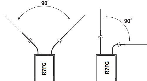
- Keep the two antenna in 90° angle as shown below
- Big models may contain metal parts that influence signal emission. In this case. antennas should be positioned at both sides of the model to ensure the best signal status in all circumstances.
- Antennas should be kept away from metal conductor and carbon fiber at least half inch away and no over bending.
- Keep antennas away from motor, ESC or other possible interference sources.
- Sponge or foam material is advised to use to prevent vibration when installing receiver.
- Receiver contains some electronic components of high-precision. Be careful to avoid strong vibration and high temperature.
- Special vibration-proof material for R/C like foam or rubber cloth is used to pack to protect receiver. Keeping the receiver in a well sealed plastic bag can avoid humidity and dust, which would possibly make the receiver out of control.
When all the above steps are complete, please turn off the transmitter and repower on to test if the receiver is correctly bind with it.
Thank you again for choosing RadioLink product.