
Introduction
Radiolink R8EF, 2.4G 8 channels receiver, S-BUS, PPM and PWM signal support, use for Radiolink transmitter T8FB,T8S,RC4GS V2,RC6GS V2.
Two signal working mode
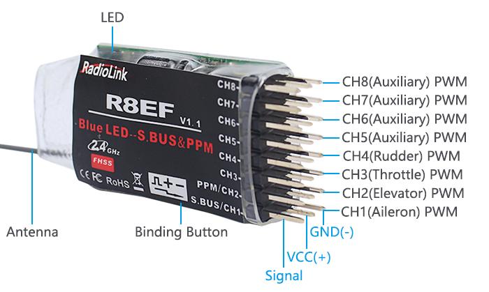
1、PWM signal output working mode
Red LED indicates PWM signal output, 8 channels Totally.
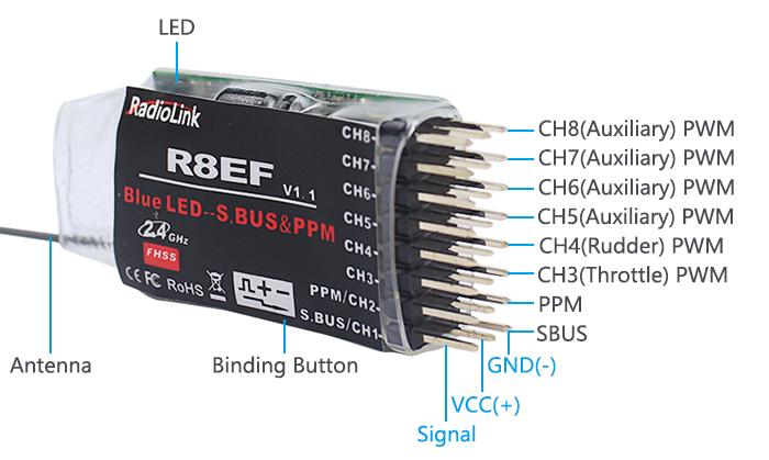
2. S-BUS&PPM signal output working mode
Blue/purple LED indicates SBUS&PPM signal output, 8 channels totally. SBUS and PWM signal possible working at the same time with S-BUS&PPM signal output working mode.
CH1 output S-BUS signal, CH2 output PPM signal, CH3 to CH8 output PWM signal at the same time.
3.S-BUS&PPM and PWM signal change
Quick press the ID SET switch twice within 1 second, the signal is changed from PWM to S-BUS&PPM. The red LED indicates the PWM and blue/purple indicates S-BUS&PPM&PWM.
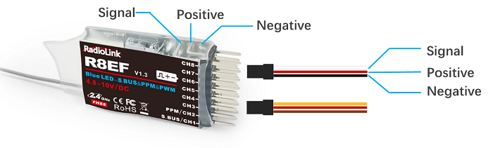
4.Receiver Connection
The connection wire for receiver is shown in the picture above. The common ones are white/red/black wire or yellow/red/brown wire. The two types of servo cables both are the light-colored wire as the signal wire, the dark-colored wire as the ground wire, and the middle is 5V power supply, and the three wires correspond to “  ”.
”.
Note:
1、Radiolink receivers are all designed with anti-polarity connect protection. When the servo cable is plugged reversely, the receiver will not work.
2、The receiver operating voltage is 4.8V-10V. When the receiver uses a separate battery for independent power supply, the receiver will not be damaged if the battery polarity is reversed, but if the servo is connected at this time, it will cause damage to the servo.
How to binding with transmitter
1. Put the transmitter and the receiver close to each other within 1 meter.
2. Turn on the transmitter, then power on the R8EF.
3. There is a black button on the R8EF, press the binding button in one second until the receiver light starts blinking and release, after about 8 times blinking, match code success when receiver signal LED always on.
Installment of receiver antenna
- The antenna must be kept as straight as possible. Otherwise, it will reduce the effective range.
- Large model aircraft may of some metal part interfering signal, in this case the antenna should be placed at side of the model.
- The antenna must be kept away from conductive materials, such as metal and carbon by at least a half inch. The coaxial part of the antenna does not need to follow these guidelines, but do not bend it in a small radius.
- Keep the antenna away from the motor, ESC, and other noise sources as much as possible.
- The receiver can be packed by sponge or foam for shocking proof when it is installed to the model.
- After all of the above steps finished, now the program functions to assure it under control of transmitter with a right connection.
Specification
Channels: 8 channels
Working voltage: 3-15V
Working current: 30mA(input voltage: 5V)
Size: 48.5*21*11mm
Weight: 7g
4096 section precision, 0.5us per section, servo anti-shake rudder.
Control distance: about 2000 meters air, actually control distance depends on the environment.