
R8FGH Introduction
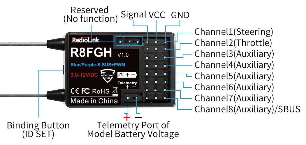
RadioLink R8FGH 2.4G 8-channel receiver, with telemetry of maximum 14S (58.8V) model battery voltage supported, splash-proof, with reverse polarity protection circuit and integrated gyro for professional car drifting and high voltage servo supported.
R8FGH receiver is compatible with RadioLink RC8X/RC6GS V3/RC4GS V3/RC6GS V2/RC4GS V2/RC6GS (3-position switch version)/RC4GS (version with P.D AFTER 180101) /T8FB(BT) /T8S(BT)/T8FB(OTG)/
T8S(OTG) transmitters.
Receiver Protocol Selection
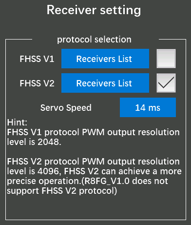
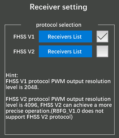
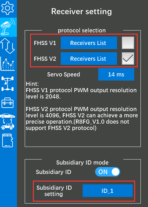
If you are using R8FGH with RC8X transmitter, please select correct receiver protocol in RC8X first and then bind them. Enter the "Basic Menu" - "Receiver setting" of RC8X and then select FHSS V1 or FHSS V2 protocol (as shown below). R8FGH supports both FHSS V1 and FHSS V2 protocol. FHSS V1 receivers have a PWM output resolution of 2048, and FHSS V2 receivers have a PWM output resolution of 4096. The higher the resolution, the more delicate the angle of servo motion. So it is recommended to select FHSS V2 protocol for R8FGH.
Note: Each time the receiver protocol is switched, please re-bind R8FGH and RC8X.
Servo Speed Setting
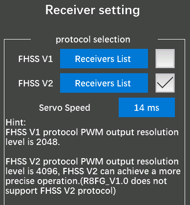
When FHSS V2 protocol is selected in RC8X, servo Speed will appear on the screen (as shown below).
Servo Speed setting method:
1、Transmitter: It is necessary to update the RC8X firmware to V1.1.5 or above, and then select FHSS V2 protocol to display this option. Servo speed can be selected from 14ms, 4ms, and 3ms. The default servo speed is 14ms (analog servo speed), 4ms and 3ms (digital servo speed).
2、Receiver: If you are using a digital servo, you need to choose a servo speed of 4ms or 3ms. The receiver needs to support digital servo. R8FGH supports digital servo.
3、Status indication: When switching the servo speed, the green LED light of the receiver will flash once, which means that the switching of the servo speed is successful; if the green LED of the receiver does not flash when switching the servo speed of the servo, it means that the switching of the servo speed of the servo fails.
Binding
Each receiver has an individual ID code and must bind with transmitter before using. When the binding is done, the ID code will be stored in the transmitter and there’s no need to rebind. Therefore, when a new R8FGH is purchased, binding needs to be done in order to work with transmitter.
Binding steps:
- Select the receiver protocol in RC8X. (Please refer to ) Note: If you are using a transmitter other than RC8X, such as RC6GS/RC4GS/T8S/T8FB, etc., go to step 2 directly.
- Put the transmitter and the receiver close to each other (about 60 centimeters).
- Turn on both the transmitter and the receiver, and then the LED of R8FGH will start flashing slowly.
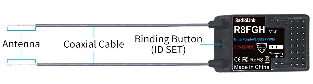
- There is a black binding button (ID SET) on the side of the receiver. Press the button for more than 1 second and release, the LED will flash quickly, indicating the binding process is ongoing.
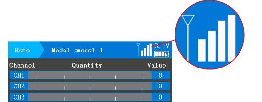
- When the LED stops flashing and is always on, binding is complete and there will be a signal tower shown on top of the IPS screen of the transmitter(As shown on the right). If not successful, the LED will keep flashing slowly to notify, repeat the above steps.
Note:
1、When the transmitter and receiver are powered on, if binding fails or the signal is lost, the LED of R8FGH will keep flashing to notify. 2、The close distance between the transmitter and receiver may cause a signal block, which leads to unsuccessful binding or signal loss. After the binding is successful, if RC8X and R8FGH receiver are too close (for example, within 60 centimeters), the signal may also be lost because of signal block. Bring RC8X transmitter and R8FGH receiver farther apart, the signal loss will disappear automatically.
Telemetry
R8FGH can return the real-time flight information such as RSSI, receiver voltage and model battery voltage.
In order to enjoy this function, please upgrade RC6GS(3-position switch version) with the firmware RC6GS_RadioLink_bin_1d15_V_6_1_2 downloaded via
Or upgrade RC4GS(produced after 2018-01-01) with the firmware RC4GS_RX_RadioLink_bin_2f50_V_6_0_1 downloaded via
If you are using RC8X, RC6GS V3, RC6GS V2, RC4GS V3 or RC4GS V2, the default firmware supports telemetry function.
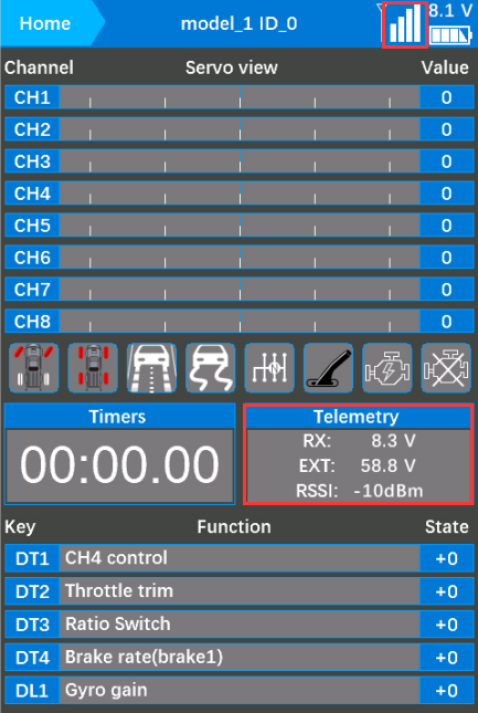
Power on RC8X and R8FGH receiver. The signal and other telemetry information will be displayed in the home page of RC8X if the binding is successful and the telemetry cable is connected correctly.
RC8X home page:
1、Telemetry of Signal and RSSI
Power on RC8X and R8FGH receiver, and then bind them. Signal and RSSI will be displayed on the homepage of transmitter after successful binding.
RC8X home page:
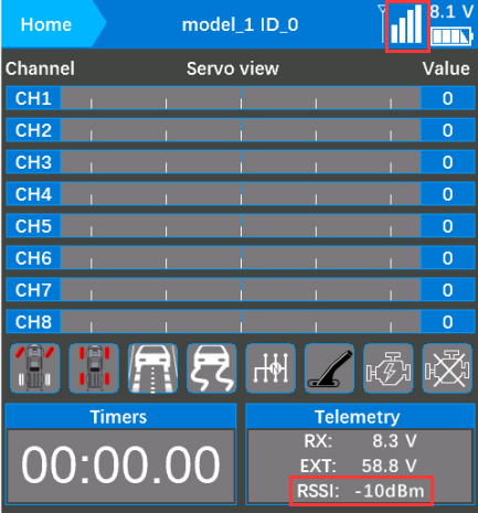
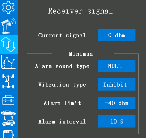
Warning can be set with a certain low RSSI value after testing by changing distance. Enter Telemetry setting--Receiver signal to set the RSSI warning value, alarm sound type etc.
Note: R8FGH is the receiver with dual antenna. When the distance between the transmitter and the R8FGH is 60 centimeters, it is normal that RSSI value is within the range of 0 to -30dBm. The closer the value is to 0, the stronger the signal is. The range of RSSI value of RadioLink transmitters is from 0 to -99dBm. The larger the absolute value of the RSSI value is, the weaker the signal is. For example, the signal when the RSSI value is -90dBm is weaker than the signal when the RSSI value is -75dBm.
2、Telemetry of model battery and receiver voltage
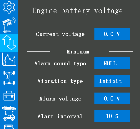
Besides the return of receiver voltage and model battery voltage R8FGH supports model battery telemetry, with maximum 14S (58.8V) battery supported. Users can personalize the warning value of low model battery voltage depending on the actual needs. Enter Telemetry setting-- Engine battery voltage to set the alarm voltage, alarm sound type etc. Normally we set the warning value with the single cell voltage to 3.7V. For example, if it is 3S lithium battery used in the model car, the warning value should be set to 11.1V (3.7V*3S=11.1V).
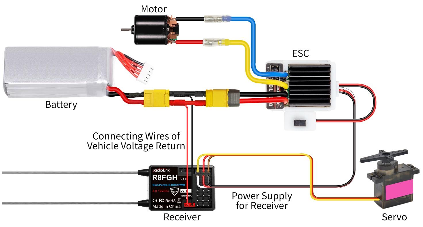
Model battery voltage return can be easily achieved by connecting the male end of the battery wire to ESC while the female end to the battery and the wire with a JST head connects Telemetry (+-) port of R8FGH as below pic shown. No extra module is needed.
Attention:
Reverse polarity protection circuit design for all 8 channels of R8FGH ensures vital components are protected from a reverse polarity connection. But, the JST connector which is packed with R8FGH for connecting to the battery cannot reverse polarity connect, or it will lead to the wrong voltage value telemetry.
Telemetry port is only used to model voltage telemetry. It can not be used to power the receiver.
Subsidiary ID
RC8X can bind with multiple receivers. When RC8X and multiple receivers have been bound successfully, and RC8X and all successfully paired devices are turned on at the same time. There are two ways to use them:
1. When Subsidiary ID function is turned off, RC8X can control multiple devices at the same time.
2. When Subsidiary ID function is turned on, RC8X can control the specified device according to the selected Subsidiary ID. RC8X has 16 groups of Subsidiary ID functions, and each ID corresponds to a receiver. Set the Subsidiary ID first. When all the devices are turned on, you can control one of the devices through the Subsidiary ID function. At this time, the other devices are on standby.
For example: Bind RC8X with a truck and a car and turn all them on. First, use RC8X to control the car to run to the bucket of the truck, and then switch the receiver ID on the truck to drag the car back to the destination.
Subsidiary ID mode setting steps:
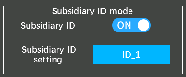
1. Tap the button at the right of the "Subsidiary ID mode" to change it from "OFF" to "ON". Set the ID number according to your cars or boats and then finish the bind and parameters set for each receiver.
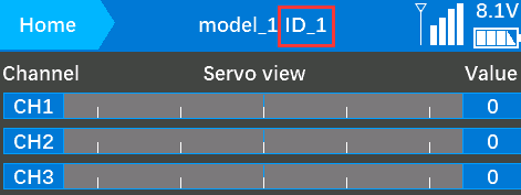
2. Once finished the Subsidiary ID mode setting, the corresponding ID number will be displayed on the main interface of RC8X. (For example: ID_1) Change the ID number by click "-" or "+", click Reset will make the ID number back to ID_0.
Note: When RC8X transmitter uses the Subsidiary ID function, please check whether the receiver protocol matches the receiver on the current sub-ID model after switching the subsidiary ID. If the receiver protocol is selected incorrectly, the binding will be lost.
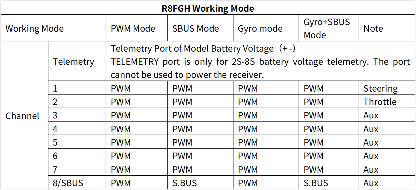
Working Modes
R8FGH has a built-in gyroscope, which can output not only PWM signals but also SBUS signals. There are four working modes, including ordinary PWM mode, SBUS mode, Gyro mode, and Gyro + SBUS mode. The channel signal corresponding to each mode is as follows:
1、Working mode setting
Turn on/off the gyro: Short press the binding button 3 times within 2 seconds to switch the gyro on and off, and the color of the LED indicator will switch accordingly
Gyro phase switch: Short press the binding button twice within 2 seconds to switch the gyro phase.
Turning on/off the SBUS: short press the binding button once to turn on/off the SBUS, and the color of the LED indicator will switch accordingly. After SBUS signal is enabled, channel 1-7 output PWM, and channel 8 outputs the SBUS signal.
2、LED Indicator Color in Different Working Modes
Working Mode | PWM Mode | Gyro mode | SBUS Mode | Gyro + SBUS Mode |
Indicator Color | Green | Red | Blue | Red+Blue |
Gyro Introduction
1 、Gyro Function
R8FGH has a built-in gyroscope. The integrated high-performance gyro adopts the software filter and PID algorithm, timely and precisely corrects the sensitivity and improves the stability. Its good flexibility to different models easily achieves professional performance even with drift cars.
2 、Gyro Enable
The gyro function of R8FGH is turned off by default. Since the integrated gyro in R8FGH will self-check, it is important to keep R8FGH still when powering it on. Red LED is the gyro status indicator . When the red LED off means NO gyro. Press the binding button three times (intervals of less than 1 second), the red LED will flash three times, indicating that gyro is enabled.
Attention: It's normal that the servo keeps shaking when connected to the receiver. Because the gyro is helping to correct the steering gear angle of the servo automatically if the gyro function has turned on, you can turn off the gyro function if you do not need this function.
If the receiver has not to be moved, but the servo keep shaking, there are two reasons below:
① The servo has connected to the SBUS channel of the receiver. Please reconnect the servo to the CH1/2/3/4/5/6/7, because the standard servo only supports PWM signal input.
② The gyro is too much sensitive. Please turn DL1 switch to reduce the gyro sensitivity.
3 、Gyro Reverse
Set the gyro forward, and turn the car right or left to see whether the gyro functions. The wheel will turn left when the car is turned right and the wheel turns right when the car is turned left. If the gyro acts counter, press the binding button twice, the red LED flashes twice, the gyro reverse is corrected.
4、Gyro Sensitivity Adjustment
When using RC8X transmitter, gyro sensitivity is defaulted to adjust by channel eight that default controlled by DL1/PS3 knob switch, turning the DL1/PS3 knob switch clockwise to increase sensitivity and anti-clockwise to reduce it. When turning the DL1/PS3 knob switch, a tooltip with yellow background color will pop out at the top of the screen, and the value of the channel will be changing at the same time, the value is closer to +100, the higher sensitivity. If the value is 0, it means the gyro function has been turned off. You can also assign other switches to adjust the gyro or adjust it on the setting interface.

When using RC4GS/RC6GS transmitter, gyro sensitivity is controlled by VR rotary switch by default. Percentage is displayed when sensitivity is adjusted while the bigger percentage means higher sensitivity. If the VR rotary switch is set with other function, MODE can be changed to STD in GYRO setting of the menu to adjust gyro sensitivity with buttons Dec(-) and Inc(-).
R8FGH Specifications
R8FGH Receiver | |
Dimension | L*W*H =35*24*13.5mm (1.38"*0.94"*0.53") |
Weight | 10.5g (0.37oz) |
Channel | 8 channels |
Antenna Length | 205mm (8.07") |
Control Distance | Ground 600 meters (1968.5ft) (Maximum range tested in unobstructed areas free of interference) |
Operating Current | 35mA (5V) |
Operating Voltage | 3-12V |
Signal Output | SBUS&PWM |
Telemetry | Real-time built-in telemetry of model battery voltage(3.0-58.8V), RSSI, and receiver voltage |
Applicable Model Types | Car (Including Crawlers/Tanks/Caterpillars)/Boat/Robot |
Gyro | Receiver with gyro integrated, customizable gyro sensitivity |
Water Splash Proof | The waterproof grade is IPX4 |
Response Latency | 3ms, 4ms, 14ms can be selected |
Compatible Transmitter | RC8X/RC6GS V3/RC4GS V3/RC6GS V2/RC4GS V2/RC6GS (3-position switch version)/RC4GS (version with P.D AFTER 180101) /T8FB(BT)/T8FB(OTG)/T8S(BT)/T8S(OTG) |
Note of Antenna Installation
In order to maximize the signal transmission, it’s greatly advised that
Please test RSSI (Received Signal Strength Indicator) before operating models. For methods on how to test it, please refer to
Please check the receiver antenna and transmitter antenna before operating models. The gray line on receiver is coaxial cable, while the transparent line with a length of about 4-5 centimeters at the top is antenna, as shown below. If the transparent line is broken or damaged, it will directly affect the control distance. If any abnormality is found, please replace the receiver antenna in time.
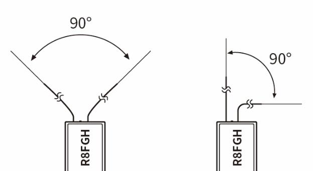
Keep antennas as straight as possible, or the effective control range will reduce.
Keep the two antenna in 90° angle as shown on the right.
Big models may contain metal parts that influence signal emission. In this case. antennas should be positioned at both sides of the model to ensure the best signal status in all circumstances.
Antennas should be kept away from metal conductor and carbon fiber at least half inch away and no over bending.
Keep antennas away from motor, ESC or other possible interference sources.
Sponge or foam material is advised to use to prevent vibration when installing receiver.
Receiver contains some electronic components of high-precision. Be careful to avoid strong vibration and high temperature.
Special vibration-proof material for R/C like foam or rubber cloth is used to pack to protect receiver. Keeping the receiver in a well sealed plastic bag can avoid humidity and dust, which would possibly make the receiver out of control.
Technical Support Here


Contact RadioLink RL R8FGH User Manual R8FGH Tutorials
via Facebook Messenger
If the above information cannot solve your problem, you can also send emails to our technical support:
This content is subject to change. Download the latest manual of R8FGH from https://www.radiolink.com/r8fgh_manual
Thank you again for choosing RadioLink product.