RC4GS
Digital 4 Channels Proportional RC System
Instruction Manual
CE FCC ROHS
Technical updates and additional programming examples available at: radiolink.com
INTRODUCTION
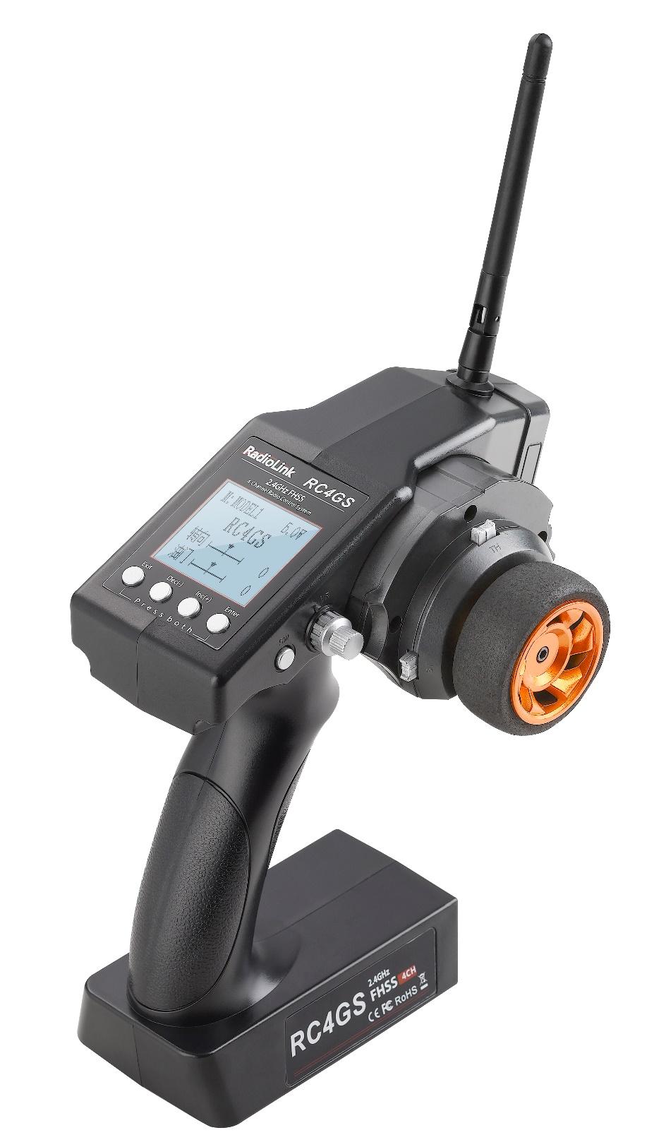
Thank you for choosing Radiolink 2.4 GHz 4CH pistol grip radio -- RC4GS.
RC4GS is default 4 channels transmitter, sells with receiver R6FG which with gyro integrated and HV
servo supported.
RC4GS, work with FHSS spread spectrum and 16 channels pseudo frequency sequence hopping, both transmitter and receiver use industrial chip ensure superior anti-interference ability both at the same frequency band and different frequency band and anti-sparks interference ability. Ground control distance is up to 400 meters.
Suggestion: In order to fully enjoy the benefits of this remote control equipment and ensure safety, please read the introduction carefully and set up the device as described below.
If you found any problems during the operation process, please refer to the manual. If the problem still exists, you could contact our dealers to find out the way to solve it. And you could also log in BBS (such as
) or call our after-sales (+86-0755-88361717) to check the issues related answer.
Due to unforeseen changes in production procedures, the information contained in this manual is subject to change without notice.
More information please check our website as below:
Support and Service: It is recommended to have your Radiolink equipment serviced annually during your hobby’s “off season” to ensure safe operation.
Please be sure to regularly visit the Service and Support web site at . This page includes extensive programming, use, set up and safety information.
Any technical updates and manual corrections will be available on this web pages. If you do not find the answers to your questions there, please see the end of our contact area for information on contacting us via email for the most rapid and convenient response.
FOR AFTER-SALES SERVICE:
Please start here for getting more service.
Phone:+86-755-88361717
Email:
FOR TECHNIQUE SUPPORT:
Please start here for answers to technique questions:
Phone:86-755-88361717
Email:
Important Safety Notice:
The following two symbols will appear in this manual(please pay attention to the paragraph with this two symbols labeled):
 Prohibition
  Testing and confirmation
 Do not use in bad weather such as rainy or thundering to assure the safety of you and others.
 Forbid to use this product in the crowd and the place against national law!
 You need to turn the throttle channel(CH3) and inch switch to the lowest before you use. Then switch on the transmitter, finally connect the receiver.
Before using, please make sure the movements of servo are corresponding with the direction of joystick. If inconsistent, please adjust them before using.
 The sequence to shut down is that turn off the receiver power first, and then shut down the transmitter. If the above operations are reverse, it might lead to uncontrolled situation and cause accidents.
The transmitter needs to be powered by 4 AA batteries or 2S-4S LiPo batteries. Please check the voltage of batteries before using, as it might lead to uncontrolled situation and accidents when the voltage is lacked. So you must change the battery or recharge them in time.
Warning!!!
This product is not a toy and is not suitable for children under the age of 18. Adults should keep the product out of the reach of children and exercise caution when operating this product in the presence of children.
Please don't run in the rain! Rain or moisture may enter the transmitter internal through gaps in the antenna or joystick and cause your car to instability even out of control. If inevitable will run in the wet weather (such as game), please be sure to use plastic bags or waterproof cloth to cover your transmitter, please don't run if there is lightning.
FCC Statement
This equipment has been tested and found to comply with the limits for a Class B digital device, pursuant to Part 15 of the FCC Rules. These limits are designed to provide reasonable protection against harmful interference in a residential installation. This equipment generates uses and can radiate radio frequency energy and, if not installed and used in accordance with the instructions, may cause harmful interference to radio communications. However, there is no guarantee that interference will not occur in a particular installation. If this equipment does cause harmful interference to radio or television reception, which can be determined by turning the equipment off and on, the user is encouraged to try to correct the interference by one or more of the following measures:
-- Reorient or relocate the receiving antenna.
-- Increase the separation between the equipment and receiver.
-- Connect the equipment into an outlet on a circuit different from that to which the receiver is connected.
-- Consult the dealer or an experienced radio/TV technician for help.
This device complies with part 15 of the FCC Rules. Operation is subject to the following two conditions:
(1) This device may not cause harmful interference, and (2) this device must accept any interference received, including interference that may cause undesired operation.
Changes or modifications not expressly approved by the party responsible for compliance could void the user's authority to operate the equipment.
CONTENTS
1. Introduction and Service……………………………………………………………………………………………….……………….1
2. Safety Notice and Warning……………………………………………………………………………………………..……….....….2
3. Pistol Grip Control System……………………………………………………….....…………………..……………..……….....…..4
3.1 Transmitter………………………………………………………………………………………………………………..………………5
3.2 Receiver……………………………………………………………………………………………………………..………………..……5
3.2.1 Receiver Installation and Binding………………………………………………………………………………………6
3.2.2 Working Mode…………………………………………………………………………………………….....…………………6
3.2.3 How to Turn On Gyro Function………………………………………………….…………….…………...……………7
4. RC4GS Functions…………………………………….………………………….…………………………….………….………..….…...8
4.1 Display When Power Switch Turned On…………………………………………………………………….……….……...8
4.2 Language Select "LANGUAGE" ………………....………………………………………….………….……………....…......9
4.3 Model Select "MODEL"……………………………………………….....……………….…....………........……….…..............9
4.4 End Point Adjuster "EPA"………………………………….…..…..……………………….…....……......……….………...…10
4.5 Steering EXP "STEXP"…………………………………….………..……………………….…....………….........…….………..11
4.6 Steering Speed "STSPD"…………………………………….….……………………….…....……………….….......…..…... 11
4.7 Throttle EXP "THEXP"……………………………………………………………………….…....…………….………..............12
4.8 Throttle Speed "THSPD"………………………………………………………………….…....…………….…………............14
4.9 A.B.S. Function "A.B.S"…………………………………………………..…………………….…....………….…....................15
4.10 Throttle Acceleration "ACCEL"…………………………………………………………….…....……………….……….....19
4.11 Idle-Up "IDLUP"………………………………………………………………………………….…....….………........…...........20
4.12 Sub-trim "SUBTR"………………………………………………………………………….…....………….……..…….............20
4.13 Servo Reverse "REV"……………………………………………………………………….…....……….…………............….21
4.14 Steering Dual Rate/Throttle Dual Rate "D/R"…………………………………………….…………………......……21
4.15 ATL Function "ATL"………………………………………………………………………………….…....…….…...……..........22
4.16 Programmable Mixes "PMIX"………………………………………………………………….…....….……………...…....22
4.17 Channel 3 Position "AUX"………………………………………..……………………………….….....……………........…24
4.18 Model Name "NAME"………………………………………………………………………….…....……….…….….............25
4.19 Low Voltage Alarm……………………………………………………..……………………….…....……….….………..........25
4.20 Gyro Sensitivity…………………………………………………………………………………….…....……….……...…..........25
4.23 Fail Safe………………………………………………………………………………….…………….…............…...…................26
4.24 Reset Function "RESET"………………………………………………………………………………….……...…................26
Pistol Grip Control System
RC4GS, transmitter with chip STM32F103RB, receiver R6FG/R6F with 32 bits industrial chip, 12ms only from transmitter to the receiver, thus provide control synchronous and performance perfect.
The same FHSS spread spectrum and 16 channels pseudo random frequency sequence hopping of AT9S makes RC4GS have superior anti-interference ability both at the same frequency band and different frequency bands.
Control distance is up to 400 meters.
3.1 Transmitter
Size: 213 *117 * 115.5mm
Frequency: 2.4Ghz ISM Band(2408.0MHz--2477.6MHz)
Channel: 4CH
Channel resolution: 4096, the regular jitter is 0.5us
Model: Cars/Boats
Modulation Mode: GFSK
Spread Spectrum: FHSS, 16 Channels Pseudo Random Frequency Sequence Hopping(the system works in the frequency range of 2408.0 to 2477.6 ,this band has been divided to 59 independent channels, each radio system uses 16 different chnnels the minimum channelseparation is >1MHz,by using various switch-on times, hopping scheme and channel frequencies, the system can guarantee a jamming free radio transmission.)
10 Modes Memory Storage
Antenna Length: 106mm
Control Distance: More than 400 meters ground
LCD Screen: 128*64 Resolution, LCD Back Light
Transmitter Operating Voltage: 4.8-15.0V DC
Transmitter Battery: 4*AA or 2-4S lithium battery
Transmitter operating current : 80-120mA
RF power: <20dbm
Low Voltage alert: Yes(lower than 4.6V), can be set when using 2-4S LiPo battery
Receiver: R6FG, R6F, R8EF, R8FM
3.2 Receiver
RC4GS, sells with R6FG, 2.4GHz 6 channels receiver, gyro integrated and HV servo supported.

Specification
Frequency: 2.4GHz ISM band(2408.0MHz--2477.6MHz
Size: 35*20*13mm
Channel: 6
Model: cars/boats
Modulation mode: GFSK
Spread spectrum: FHSS
10 modes memory storage
Antenna length: 200mm
Control distance: more than 400 meters
LCD screen: 128*64 resolution, LCD back light
Power supply: 4.8~10.0V DC
RF power: <10dbm
Channel resolution: 4096
Work current: 30mA
3.2.1 Receiver Installation and Binding
How to Match Code With Transmitter:
1. Put the transmitter and the receiver close to each other within 50 centimeters.
2. Turn on the transmitter, then power on the R6FG.
3. There is a black button on the R6FG, press the binding button twice in two seconds and release, receiver light start blinking, after about blinking 8 times, match code success then receiver signal LED always on!
Attention: R6FG default have not turn on the gyro function. Make sure the R6FG keep motionless when power on it, because the R6FG will do the self-test.
R6FG with two indicate LED, green LED on indicate normal working mode while both green and red LED on indicate gyro function working mode.
3.2.2 Working Mode
R6FG has two working modes:normal working mode and gyro function working mode.
Normal Working Mode
Green LED, gyro will not working.
Gyro Function Working Mode
Both green and red LED on.
Receiver with gyro integrated to hold the vehicle in a straight line during aggressive acceleration and braking or get bumped around by rough terrain.
Receiver with gyro integrated to keep the uni-direction and anti-slip.
3.2.3 How to Turn On Gyro Function
Quick press the ID SET switch two times within 1 second, the LED change from green to red means gyro function has turn on.
Gyro Function Setup
Integrated Gyro, is used to assure the stability of cars on turning status; and keep on straight running even the cars get some mechanical phantom. Gyro function can be enabled or disabled.
A. Gyro enabled
Gyro preset disabled, and it enters post indication status. There are two indicators on the receiver. The green one shows the receiver status and the red one is for gyro. When the led turns on, the gyro is enabled , and the led turns off, gyro disabled.
B. Gyro enabled forward
Cars can be drove forward and backward, gyro is enabled forward or backward correspondingly. Like the EP cars, different connection will make different direction, the gyro is ensured to be enable forward.
C. Gyro reverse
Same like a plane has reverse, car kit gyro has reverse as well. Only right set reverse gyro can act to correct.
Setup
(1) Enable gyro
Press binding key three time (interval less than 1 second), the red LED will flash three time, indicating whether gyro is enabled.
(2) Gyro sensitivity
Gyro sensitivity is predefined to adjust by channel three (factory set VR function), turning the VR switch clockwise to raise sensitivity and anti-clockwise to decrease.
(3) Gyro forward
When the gyro is enabled, pull the throttle trigger and then release (make sure the car stops running), turn the car right or left without changing steering wheel, if the servo will not follow with, it shows gyro is set backward. Press the binding switch one time less than 1 second, the LED flashes red once, gyro is changed to act forward.
(4) Gyro reverse
Set the gyro forward, turn the car right or left to see whether gyro functions. The wheel will turn left when the car is turned right and the wheel turns right when the car is turned left. If the gyro acts counter, press the binding switch two time, the LED flashes two time red, the gyro reverse is corrected.
Installment of receiver antenna:
The antenna must be kept as straight as possible. Otherwise it will reduce the effective range.
Large model aircraft may of some metal part interfering signal; in this case the antennas should be placed at both sides of the model. Then the best RF signal condition is obtained at any flying attitude.
The antennas must be kept away from conductive materials, such as metal and carbon by at least a half inch. The coaxial part of the antennas does not need to follow these guidelines, but do not bend it in a small radius.
Keep the antennas away from the motor, ESC, and other noise sources as much as possible.
Press and hold the Easy Link (ID SET) one second, now the receiver starts work.
After all of the above steps finished, the LED indicator will turn and keep in red/green.
The receiver can be packed by sponge or foam for shocking proof when it is installed to the model.
After all of the above steps finished, turn off the transmitter and then power it on, now the program functions to assure it under control of transmitter with a right connection.
4. RC4GS Functions
4.1 Display When Power Switch Turned On
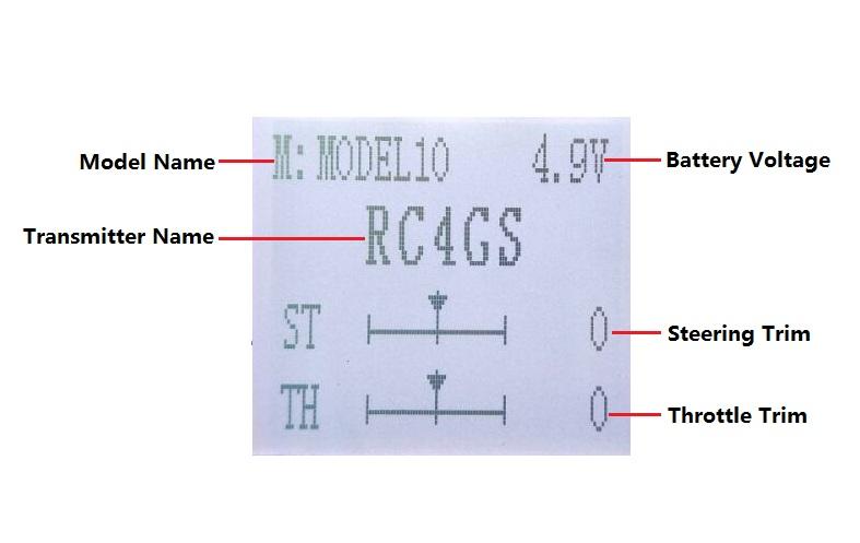
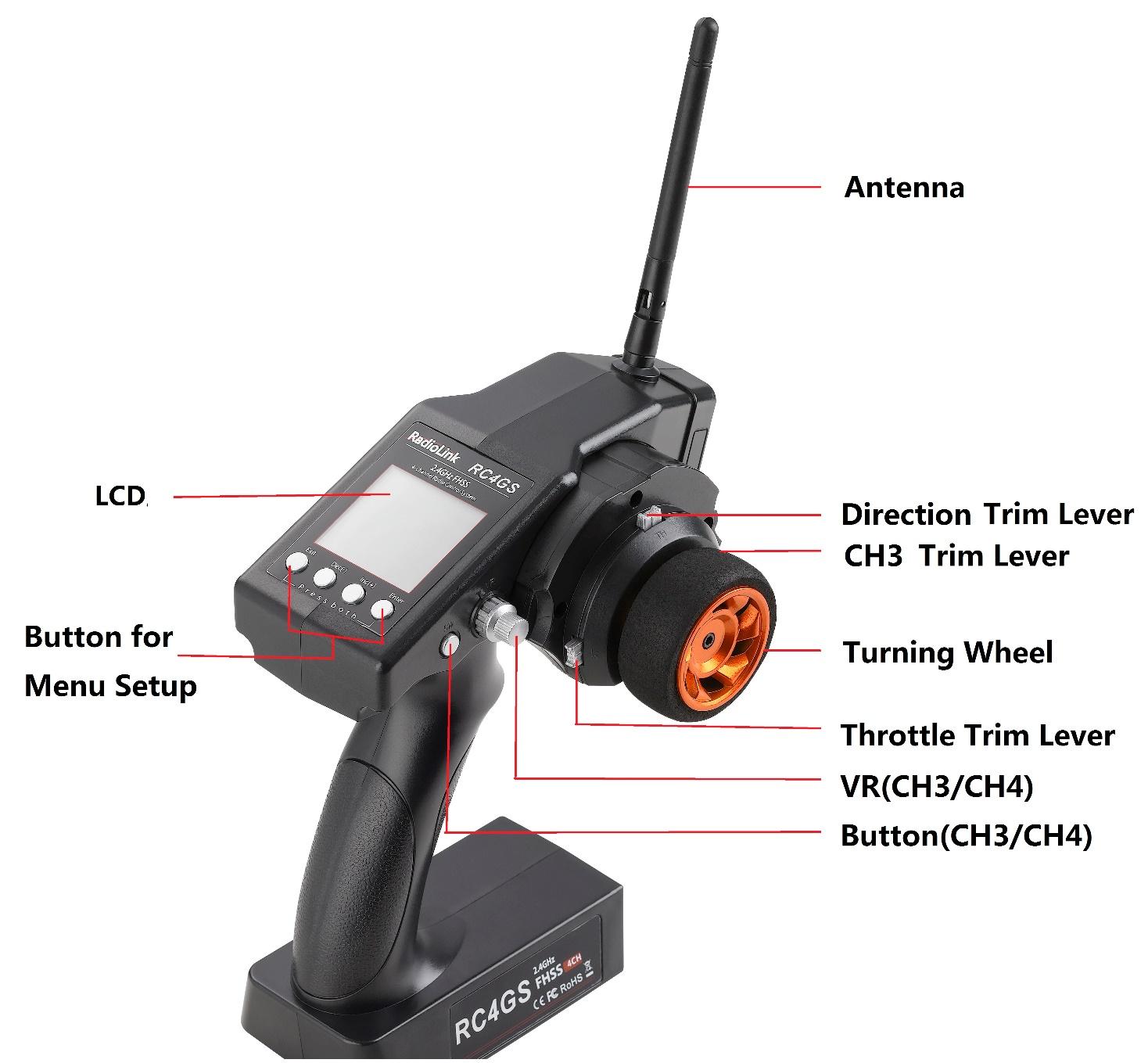
LCD Screen
When you power on the transmitter, LCD screen shows Model Name, Transmitter Name, Battery Voltage, Steering Trim, Throttle Trim.
Model Name
The system can store the data for 10 models, model name will show on the LCD when you power on the transmitter. Please make sure the model name is the right one that you want.
If the model name you chose is not corresponding with your model, the settings should be wrong.
Battery Voltage
In addition to the model, LCD can show the voltage of battery. When the voltage is lower than 4.6V, it would start the low-voltage alarm, it would send out “DDD…” sounds, till the transmitter is power-off. When you hear the low-voltage alert, you have no more than 4 minutes for controlling your model, please safely stop your model before the uncontrolled situation. Please make sure the battery voltage is higher than this voltage data while radio controlling.
Transmitter function menu setting
When you want to browse or change a setting of transmitter, you should go into function menu setting mode. Under function menu setting mode, you can set up Language. Select "LANGUAGE" , Model Select "MODEL", End Point Adjuster "EPA", Steering EXP "STEXP", Steering Speed "STSPD", Throttle EXP "THEXP", Throttle Speed "THSPD", A.B.S. Function "A.B.S", Throttle Acceleration "ACCEL", Idle-Up "IDLUP", Sub-trim "SUBTR", Servo Reverse "REV", Steering Dual Rate/Second. Dual Rate "D/R", ATL Function "ATL", Programmable Mixes "PMIX", Auxiliary, Channel 3 and 4 "AUX",Model name "NAME", Reset function "RESET".
4.2 Language Select "LANGUAGE"
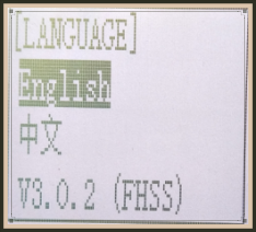 Both English and Chinese version menu are available for which is convenient for Chinese and English-speaking players to personalize function menus.
(1) Access the function menu (By pressing “Exit” and “Enter”buttons simultaneously and holding them down for one second), the Language select function will be chosen.
(2) Press “Enter” button to get into “LANGUAGE” function interface.
(3) Use“Dec(-)”or “Inc(+)”key to select “中文”or “English”, the selected language will be with black shading effect.
(4) Press “Enter” button, the desired language is selected, and return to the initial screen automatically.
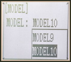 4.3 Model Select "MODEL"
RC4GS can store model memories for ten models. Use this function to call a new model.
(1) Access the function menu (By pressing “Exit” and“Enter” buttons simultaneously and holding them down for one second), press “Enter” key once, the Model select function will be chosen.
(2) Press “Enter” button, the current active model will be blinking.
(3) To activate a different model by pressing “Dec(-)” or “Inc(+)” button until the desired model blinks.
(4) Press “Enter” button, the selected model stops blinking, now the model has been selected.
(5) Return to the initial screen by pressing “Exit” button twice.
4.4 End Point Adjuster "EPA"
Use EPA when performing left and right steering angle adjustments, throttle high side/brake side operation amount adjustment, and channel 3 servo up side/down side operation amount adjustment during linkage.
Correct the maximum steering angle and left and right steering angles when there is a difference in the turning radius due to the characteristics, etc. of the vehicle.
Setting item (channel and direction)
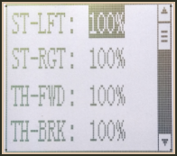 ST-LFT: Steering (left)
ST-RGT: Steering (right)
TH-FWD: Throttle (forward)
TH-BRK: Throttle (brake)
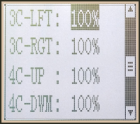
3C-LFT: 3rd channel (left)
3C-RGT: 3rd channel (right)
4C-UP: 4th channel (up)
4C-DWN: 4th channel (down)
 Steering EPA Throttle EPA
ST-LFT:0%~120% TH-FWD:0%~120%
ST-RGT:0%~120% TH-BRK:0%~120%
Initial value:100% Initial value : 100%
Aux Servo EPA Aux Servo EPA
3C- LFT:0%~120% 4C-UP:0%~120%
3C-RGT:0%~120% 4C-DWN:0%~120%
Initial value: 100% Initial value: 100%
End point adjustment
(1) Access the function menu (By pressing “Exit” and “Enter” buttons simultaneously and holding them down for one second),press “Inc(+)” button twice to chose EAP function.
(2) Press “Enter” button to get into EPA function interface, use “Dec(-)” or “Inc(+)” button to select the desired setting item , press “Enter” key, the initial value of your selected setting item will blink, then you can press “Dec(-)” or “Inc(+)” button to adjust the value of your selected setting item.
(Note: In the interface of adjusting the value, return to the initial value "100%" by pressing “Dec(-)” and “Inc(+)” buttons simultaneously for about 1 second.)
3. Press “Enter” button, the adjusted value of your selected setting item stops blinking, now the value of your selected setting item has been set.
Return to the initial screen by pressing “Exit” button twice.
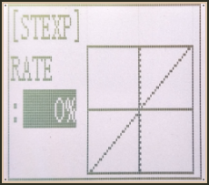
4.5 Steering EXP "STEXP"
This function is used to change the sensitivity of the steering servo around the neutral and both ends position. It has no effect on the maximum servo travel.
Adjust the sensitivity of direction wheel both in neutral position and ends.
Setup Item
RATE: Steering EXP rate
Adjustment range
-100%~0%~+100%
Initial value: 0%
0%~-100%: Sensitivity around neutral position is low, getting higher when approaching ends.
0%: Sensitivity around the neutral and ends position is equal
0%~+100%: Sensitivity around neutral position is high, getting lower when approaching ends
Steering operation curve adjustment
(1) Access the function menu (By pressing “Exit” and “Enter ”buttons simultaneously and holding them down for one second ), press “Inc(+)” button three times to chose EAP function.
(2) Press “Enter” button to get into STEXP function interface, press “Enter”key and the initial value of the rate will blink, then you can press “Dec(-) ”or “Inc(+)”button to adjust the value and the curve of the rate shown in the figure will change correspondingly.
(Note: In the interface of adjusting the value, return to the initial value "0%" by pressing “Dec(-)” and“Inc(+)” buttons simultaneously for about 1 second.)
(3) Press “Enter” button, the adjusted value of the rate stops blinking, now the value of the rate has been set.
(4) Return to the initial screen by pressing“Exit” button twice.
Note: the Vertical cursor shown in the figure moves in step with steering wheel operation.
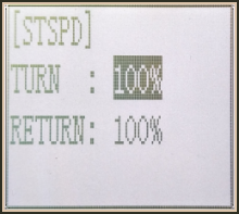 4.6 Steering Speed "STSPD"
Quick steering operation will cause momentary under steering, loss of speed, or spinning. This function is effective in such cases.
Setup item
TURN: turn direction
RETURN: return back to the original direction
Adjustment range
0%~100% (each direction)
At 100%, there is no delay
Steering servo delay
(1) Access the function menu (By pressing “Exit” and “Enter” buttons simultaneously and holding them down for one second), press “Inc(+)” button four times to chose STSPD function.
(2) Press“Enter” button to get into STSPD function interface, press “Dec(-)” or“Inc(+)” button to select setup item, then press “Enter” key and the initial value of selected setup item will blink.
(3) Use“Dec(-)” or “Inc(+)” button to adjust the value of the selected setup item.
(Note : In the interface of adjusting the value, return to the initial value "100%" by pressing“Dec(-)” and“Inc(+)” buttons simultaneously for about 1 second.)
(4) Press “Enter”button, the adjusted value of the selected setup item stops blinking, now the value of the selected setup item has been set.
(5) Return to the initial screen by pressing “Exit” button twice.
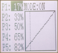
4.7 Throttle EXP "THEXP"
This function makes the throttle high side and brake side direction servo operation quicker or milder. It has no effect on the servo maximum operation amount. For the high side, selection from among three kinds of curves (CRV/VTR/EXP) is also possible.
The curve can be divided into: Five dots throttle curve adjustment, Single point adjustment,
Exponential curve adjustment, Braking index curve adjustment. To elevation point,
we can select(Exponential curve/Single point curve/Five points curve).
Curve point adjustment(select five points 1-5)
(1) Press"Enter" button,The curve point value start flashing,then press"Dec(-)"and"Inc(+)" button to adjust the starting value.
(2) Press "Enter" button ,starting value stop flashing,adjustment is completed.
(3) Press "Exit" button for two times,back to the initial interface.
Throttle curve adjustment
Adjustment method for CRV curve
Setup Items
Mode: ON/OFF
RATE: 0%~100%
1. Enter the function menu and use“ Dec(-) ” or “ Inc(+) ”button to access THEXP function. Select “FWD-CRV” function.
2. Press “Dec(-)” or “Inc(+)” button to select curve points 1~5 for curve point adjustment that you want, from the graph you will clearly see the changes you have made.
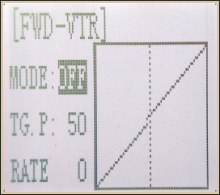 Adjustment method for VTR curve
Adjustment range
TG.P: 20-80
RATE: -100~0~+100
Enter the function menu and use “Dec(-)” or“Inc(+)”button to access THEXP function. Select“FWD-VTR” function.
Press “Dec(-)” or “Inc(+)” button to select RATE for forward side adjustment that you want, when the “MODE” value is “OFF” the VTR will not work, only the “MODE” value set to “ON” the VTR function is available. From the graph you will clearly see the changes you have made on TG.P and RATE.
 Adjustment method for EXP curve
Setup items
MODE: EXP turn on or turn off
RATE: EXP rate
Adjustment range
MODEL: OFF/ON
RATE: -100 ~ 0 ~ +100
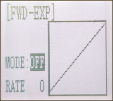
1. Enter the function menu and use “Dec(-)” or “Inc(+)” button to access THEXP function, then select the “FWD-EXP” function.
2. Press “Dec(-)” or “Inc(+)” button to select RATE for adjustment, set the most comfortable value you want. From the graph you will clearly see the changes you have made on the EXP RATE, also move the trigger to check the throttle status.
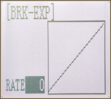
Adjustment method for BRK-EXP curve
Setup Items
RATE: BRK-EXP rate
Adjustment range
RATE: -100 ~ 0 ~ +100
0~-100: flat braking
0: uniform braking
0~+100: sensitive braking
Brake side adjustment (select BRK)
Press “Enter” key, the current BRK value will blink, use “Inc(+)” button to adjust the + side when you want to quicker the rise and use“Dec(-)” button to adjust the - side when you want to make the rise milder.
(Note: In the interface of adjusting the value, return to the initial value "0" by pressing “Dec(-)” and “Inc(+)” buttons simultaneously for about 1 second.)
Press “Enter” button, the adjusted BRK value stops blinking, now the BRK value has been set.
When ending setting, return to the initial screen by pressing “Exit” button twice.
4.8 Throttle Speed "THSPD"
Throttle servo delay
 Sudden trigger operation on a slippery road only causes the wheels to spin and the vehicle cannot accelerate smoothly. Setting the throttle speed function reduces wasteful battery consumption while at the same time permitting smooth, enjoyable operation.
Operation
Throttle servo(amp )operation is delayed so that the drive wheels will not spin even if the throttle trigger is operated more than necessary. This delay function is not performed when the throttle trigger is returned and at brake operation.
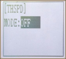
OFF: Speed1 or speed2 can be selected.
OFF means shut down the throttle speed function
Adjustment method for SPEED1
Setup items
MODE: Speed type selection
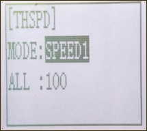 ALL: Speed adjustment
Adjustment range
0~100 (each direction)
At 100, there is no delay
(1) Enter the function menu and use “Dec(-)”or“Inc(+) ” button to access THSPD function.
(2) Press “Enter” button to get into THSPD function interface.
(3) If initial MODE setup item is SPEED1, {if initial MODE setup item is SPEED2 or OFF, you need to select SPEED1 by pressing“Dec(-)” or “Inc(+)”button to select MODE setup item , then press “Enter” key, SPEED2 or OFF will blink, press “Dec(-)” or “Inc(+)” button, when the blinking SPEED 2 or OFF change to blinking SPEED 1, press “Enter” key, SPEED1 will stop blink, now SPEED1 is selected}, press “Dec(-)” or “Inc(+)” button to select ALL setup item, then press“Enter” key, the initial value will blink, use“Dec(-)”or“Inc(+)” button to adjust the delay of the entire throttle forward side range.
(Note: In the interface of adjusting the value, return to the initial value "100" by pressing “Dec(-)” and “Inc(+)” buttons simultaneously for about 1 second.)
Press “Enter” button, the adjusted value stops blinking, now the value has been set.
When ending setting, return to the initial screen by pressing “Exit” button twice.
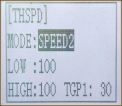
Adjustment method for SPEED2
 Setup items
MODE: Speed type selection
LOW: Low side range speed adjustment
HIGH: High side range speed adjustment
TGP1: Low and medium speed switching point
Adjustment range
LOW: 0~100
HIGH: 0~100
At 100, there is no delay
TGP1: 0~100
(1) Enter the function menu and use “Dec(-)”or “Inc(+) ” button to access THSPD function.
(2) Press “Enter” button to get into THSPD function interface.
(3) If initial MODE setup item is SPEED 2,{ if initial MODE setup item is SPEED 1, you need to select SPEED2 by pressing “Dec(-)” or “Inc(+)” button to select MODE setup item, then press “Enter” key, SPEED1 or OFF will blink, press “Dec(-)” or “Inc(+)” button, when the blinking SPEED1 or OFF change to blinking SPEED2, press “Enter” key, SPEED2 will stop blinking, now SPEED2 is selected}, press “Dec(-)” or “Inc(+)” button to select "LOW" or "HIGH" delay adjustment or“TGP1” speed switching point adjustment.
(4) Press “Enter” key to confirm "LOW" or "HIGH" or “TGP1” setup item, and the value of your selected setup item will blink. Use “Dec(-)” or “Inc(+)” button to adjust the value.
(Note: In the interface of adjusting the value, return to the initial value (the initial value of LOW and HIGH is “100”, the initial value of TGP1 is “30”) by pressing “Dec(-)” and “Inc(+)” buttons simultaneously for about 1 second.)
Press “Enter” button, the adjusted value stops blinking, now your selected value has been set.
(5) When ending setting, return to the initial screen by pressing “Exit” button twice.
4.9 A.B.S. Function "A.B.S"
Pulse brake
When the brakes are applied while cornering with a 4 Wheel Drive or other type of vehicle, under-steer may occur. The generation of under-steer can be eliminated and corners can be smoothly cleared by using this function.
Operation
- When the brakes are applied, the throttle servo will pulse intermittently. This will have the same effect as pumping the brakes in a full size car.
- The brake return amount, pulse cycle, and brake duty can be adjusted.
- The region over which the ABS is effective can be set ac-cording to the steering operation. (Mixing function)
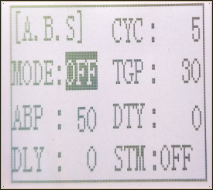 Setup items
ABP: Brake return amount
DLY: Delay amount
CYC: Cycle speed
TGP: Operation point
DTY: Cycle duty ratio
STM: Steering mixing
-ABP(Amount of brake return): Sets the rate at which the servo returns versus trigger operation for brake release. When set to 0, the ABS function is not
Performed. When set to 50, the servo returns 50% (1/2)of the trigger operation amount and when set to 100, the servo returns to the neutral position.
-DLY(Delay): Sets the delay from brake operation to ABS operation. When set to 0, the ABS function is
activated without any delay. At 50%, the ABS function is activated after a delay of approximately 0.7 second and at 100, the ABS function is activated after a delay of approximately 1.4 seconds.
-CYC(Pulse speed): Sets the pulse speed (cycle). The smaller the set value, the faster the pulse cycle.
- TGP(Trigger point): Sets the trigger point at which the ABS function begins to operate at brake operation.
-DTY(Cycle duty ratio): Sets the proportion of the time the brakes are applied and the time the brakes are released by pulse operation. The ratio can be set to +3 ~ 0~-3 in 7steps.
- STM(Steering mixing): Sets ABS operation ON/OFF according to the steering operation range.
A.B.S function adjustment
Enter the function menu and use “Dec(-)” or “Inc(+)” button to access A.B.S function, then press“Enter” button to get into A.B.S function interface.
(1) Brake return amount adjustment
Select the setting item "ABP" by pressing “Dec(-)” or “Inc(+)” button, then press “Enter” key and the initial value of “ABP” will blink. Use “Dec(-)”or“Inc(+)”button to adjust the return amount.
(Note: In the interface of adjusting the value, return to the initial value "50" by pressing “Dec(-)” and “Inc(+)” buttons simultaneously for about 1 second.)
Press “Enter” button, the adjusted value stops blinking, now the value has been set.
"0": No return
"50": Return to the 50% position of the brake operation amount
"100": Return to the neutral position.
Brake return amount (ABP)
0 ~ 50 ~ 100
Initial value: 50
- Brake return amount (ABP) is influenced by the "EXP" rate on the brake side.
(2) Delay amount setup
Select the setting item "DLY" by pressing “Dec(-)” or “Inc(+)” button, then press “Enter” key and the initial value of “DLY” will blink. Use “Dec(-)”or “Inc(+)”button to adjust the delay amount.
(Note: In the interface of adjusting the value, return to the initial value "0" by pressing “Dec(-)” and “Inc(+)” buttons simultaneously for about 1 second.)
Press “Enter” button, the adjusted value stops blinking, now the value has been set.
"0": A.B.S. function performed without any delay
"50": A.B.S function performed after an approximate 0.7 sec delay
"100": A.B.S. function performed after an approximate 1.7 secs delay
Delay amount (DLY)
0 ~ 100
Initial value; 0
(3) Pulse speed adjustment
Select setting item "CYC" by pressing “Dec(-)” or “Inc(+)” button, then press “Enter” key and the initial value of “CYC” will blink. Use “Dec(-)” or “Inc(+)”button to adjust the pulse speed (cycle).
(Note: In the interface of adjusting the value, return to the initial value "5" by pressing“Dec(-)” and “Inc(+)” buttons simultaneously for about 1 second.)
Press “Enter” button, the adjusted value stops blinking, now the value has been set.
- The smaller the set value, the faster the pulse speed.
Cycle speed (CYC)
0 ~ 30
Initial value: 5
(4) Operation point setup
Select setting item "TGP" by pressing “Dec(-)” or “Inc(+)” button, then press “Enter” key and the initial value of “TGP” will blink. Use “Dec(-)” or “Inc(+)”button to adjust the operation point.
(Note: In the interface of adjusting the value, return to the initial value "30" by pressing “Dec(-)” and “Inc(+)” buttons simultaneously for about 1 second.)
Press “Enter” button, the adjusted value stops blinking, now the value has been set.
- Sets the throttle trigger position at which the A.B.S. function is performed. The number is the 100 display with the full brake position made 100%.
Operation point (TGP)
0 ~ 100
Initial value: 30
(5) Cycle duty ratio setup
Select setting item "DTY" by pressing “Dec(-)” or “Inc(+)” button, then press“Enter” key and the initial value of “DTY” will blink. Use “Dec(-)” or “Inc(+)”button to adjust the duty ratio.
(Note: In the interface of adjusting the value, return to the initial value "0" by pressing “Dec(-)” and “Inc(+)” buttons simultaneously for about 1 second.)
Press “Enter” button, the adjusted value stops blinking, now the value has been set.
"-3": Brake application time becomes shortest. (Brakes lock with difficulty)
"+3": Brake application time becomes longest (Brakes lock easily)
(Remark) For low grip set at the - side and for high grip set at the + side.
Duty ratio (DTY)
-3 ~ 0 ~ +3
Initial value: 0
(6) Steering mixing setup
Select setting item "STM" by pressing“Dec(-)”or“Inc(+)”button, then press“Enter” key and the initial value of “STM”will blink. Use “Dec(-)”or “Inc(+)”button to adjust the steering mixing range.
(Note: In the interface of adjusting the value, return to the initial value "OFF" by pressing “Dec(-)” and “Inc(+)” buttons simultaneously for about 1 second.)
Press“Enter”button, the adjusted value stops blinking, now the value has been set.
-Sets the range within which the A.B.S. function is performed relative to steering wheel operation.
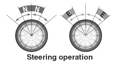
Steering mixing (STM)
OFF, N10 ~ N100, E10 ~ E100
Initial value: OFF
When steering mixing is set and steering operation enters the set range, "*" is displayed in front of the number. When mixing is OFF, the A.B.S function can operate over the entire steering range.
When ending setting, return to the initial screen by pressing “Exit” button twice.
4.10 Throttle Acceleration "ACCEL"
Function which adjusts the movement characteristic from the throttle neutral position.
The servo will jump to the input position at its maximum possible speed. Unlike exponential, which adjusts the whole throttle movement into a curve, throttle acceleration simply "jumps" away from neutral and then leaves the remaining response linear.
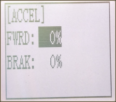
Setup item
FWRD: Forward side acceleration amount
BRAK: Brake side acceleration amount
Throttle acceleration adjustment
Enter the function menu and use “Dec(-)” or “Inc(+)” button to access ACCEL function, then press “Enter” button to get into ACCEL function interface.
(1) Forward acceleration amount adjustment
Press “Dec(-)” or “Inc(+)” button to select “FWRD”, press“Enter”key to confirm and the initial value of “FWRD” will blink, then use “Dec(-)”or“Inc(+)” button adjust the acceleration amount.
(Note: In the interface of adjusting the value, return to the initial value "0%" by pressing “Dec(-)” and “Inc(+)” buttons simultaneously for about 1 second.)
Press“Enter”button, the adjusted value stops blinking, now the value has been set.
"0%": No acceleration
"100%": Maximum acceleration(Approximately1/2of the forward side steering angle)
Forward acceleration amount(FWRD)
0%~100%
Initial value: 0%
(2) Brake side acceleration amount adjustment
Press “Dec(-)” or “Inc(+)” button to select “ BRAK ”, press“Enter”key to confirm and
the initial value of “BRAK” will blink, then use“Dec(-)”or“Inc(+)”button adjust the acceleration amount.
(Note: In the interface of adjusting the value, return to the initial value"0%" by pressing
“Dec(-)” and “Inc(+)” buttons simultaneously for about 1 second.)
Press “Enter” button, the adjusted value stops blinking, now the value has been set.
"0%": No acceleration
"100%": Maximum acceleration (Brake side maximum steering angle)
Brake side acceleration amount(BRAK)
0%~100%
Initial value: 0%
When ending setting, return to the initial screen by pressing “Exit” button twice.
4.11 Idle-Up "IDLUP"
Idle up at engine start
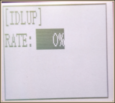 Use this function to improve the starting characteristics of the engine by raising the idling speed when starting the engine of a gas powered car.
Idle-Up rate (RATE)
-50% ~ -1%, 0%, +1% ~ +50%
Initial value: 0%
"-": Brake side
"+": Forward side
Idle-Up "IDLUP"
(1) Enter the function menu and use “Dec(-)” or“Inc(+) ” button to access IDLUP function.
(2) Press “Enter” button to get into IDLUP function interface.
(3) Press “Enter” key, and the initial value of RATE will blink. Use“ Dec(-) ” or “Inc(+)” button to adjust the value.
(Note: In the interface of adjusting the value, return to the initial value "0%" by pressing “Dec(-)” and “Inc(+)” buttons simultaneously for about 1 second.)
Press “Enter”button, the adjusted value stops blinking, now the value has been set.
(4) When ending setting, return to the initial screen by pressing “Exit”button twice.
4.12 Sub-trim "SUBTR"
Servo center position adjustment
Use this function to adjust the neutral position of the steering, throttle and channel 3 servos.
Channel
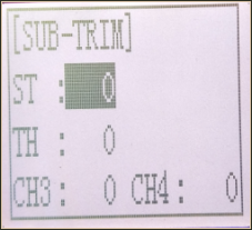 ST: Steering
TH: Throttle
CH3: Channel3
CH4: Channel4
Sub-trim
ST: -100~0~+100
TH: -100~0~+100
CH3: -100~0~+100
CH4: -100~0~+100
Initial value : 0
(1) Enter the function menu and use “Dec(-)”or “Inc(+)” button to access SUBTR function.
(2) Press “Enter” button to get into SUBTR function interface.
(3) Use “Dec(-)” or “Inc(+)” button to select ST channel, press “Enter”key, and the initial value of ST will blink. Use “Dec(-)” or “Inc(+)” button to adjust the center.
(Note: In the interface of adjusting the value, return to the initial value "0" by pressing “Dec(-)” and “Inc(+)” buttons simultaneously for about 1 second.)
(4) Press “Enter” key, the adjusted value stops blinking, now the center of ST has been adjusted.
(5) TH channel and CH3 can be set similarly.
(6) When ending setting, return to the initial screen by pressing “Exit” button twice.
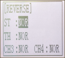
4.13 Servo Reverse "REV"
Servo operation reversing
This function reverses the direction of operation of the servos related to transmitter steering, throttle, channel 4 and channel 3 operation.
Channel
ST: Steering
TH: Throttle
CH3: Channel3
CH4: Channel4
(1) Enter the function menu and use “Dec(-)” or“Inc(+)” button to access REV function.
(2) Press “Enter” button to get into REV function interface.
(3) Use “Dec(-)” or “Inc(+)” button to select ST channel, press “Enter”key, and the “NOR” will blink.
(4) Press “Enter” key, the “NOR” stops blinking, Use “Dec(-)”or“Inc(+)”button to reverse the ST servo operation direction.
(5) TH channel, CH3 and CH4 channel can be set similarly.
(6) When ending setting, return to the initial screen by pressing “Exit” button twice.
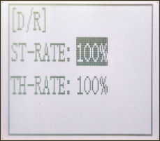
4.14 Steering Dual Rate/Throttle Dual Rate "D/R"
Dual rate
The steering left and right servo travels are adjusted simultaneously. When you want to increase the servo travel, adjust the + side. When you want to decrease the servo travel, adjust the - side.
Setup Item
Steering D/R
Throttle D/R
RATE
Steering D/R rate (RATE)
0%~100%
Initial value: 100%
Throttle D/R rate (Throttle D/R RATE)
0%~100%
Initial value: 100%
(1) Enter the function menu and use “Dec(-)” or “Inc(+)” button to access D/R function.
(2) Press“Enter” button to get into D/R function interface.
(3) Use “Dec(-)” or “Inc(+)” button to select Steering D/R RATE, press “Enter”key, and the initial value of Steering D/R RATE will blink. Use“Dec(-)”or “Inc(+)” button to make adjustments.
(Note: In the interface of adjusting the value, return to the initial value"100%" by pressing“Dec(-)” and “Inc(+)” buttons simultaneously for about 1 second.)
(4) Press “Enter” key, the adjusted value stops blinking, now the steering D/R RATE has been set.
(5) Throttle D/R RATE can be set similarly.
(6) When ending setting,return to the initial screen by pressing “Exit” button twice.
4.15 ATL Function "ATL"
Brake side adjustment
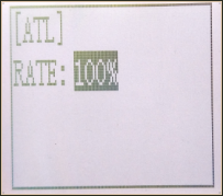 This function decreases the set value when the braking effect is strong and increases the set value when the braking effect is weak.
Setup Item
RATE: Brake amount
Brake amount (RATE)
0%~100%
Initial value: 100%
(1) Enter the function menu and use “Dec(-)” or “Inc(+)”button to access ATL function.
(2) Press “Enter” button to get into ATL function interface.
(3) Press “Enter” key, and the initial value of RATE will blink. Use “Dec(-)”or“Inc(+)” button to adjust the value.
(Note: In the interface of adjusting the value, return to the initial value "100%" by pressing “Dec(-)” and “Inc(+)” buttons simultaneously for about 1 second.)
Press “Enter” button, the adjusted value stops blinking, now the value has been set.
(4) When ending setting, return to the initial screen by pressing“Exit” button twice.
4.16 Programmable Mixes "PMIX"
Programmable mixes between arbitrary channels
These functions allow you to apply mixing between the steering, throttle, CH3 and CH4.
Setup items
LEFT: Mixing rate (Left side)
RGHT: Mixing rate (Right side)
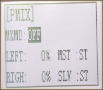 MST: Master channel
SLV: Slave channel
Programmable Mixes "PMIX"
MXMD:Mix mode
Enter the function menu and use“Dec(-)”or “Inc(+)” button to access PMIX function, then press “Enter” button to get into PMIX function interface.
(1) Master channel
Channel selection (MST)
ST, TH, CH3, CH4
Initial value: ST
Select setup item"MST" by pressing “Dec(-)” or“Inc(+)”button, press“ Enter ” button, the initial master channel will blink. Use“ Dec(-)”or“ Inc(+) ” button to select the master channel you wish to adjust, press“Enter” button,the blinking master channel you selected will stop blinking.
(2) Slave channel
Channel selection (SLV)
ST, TH, CH3, CH4
Initial value: ST
Select setup item "SLV" by pressing “Dec(-)” or “Inc(+)” button, press “Enter” button, the initial slave channel will blink. Use “Dec(-)” or “Inc(+)”button to select the slave channel you wish to adjust, press “Enter” button, the blinking slave channel you selected will stop blinking.
(3) Left, forward or up side mixing amount adjustment
Mixing amount
-100~0~+100
Select the setting item "LEFT", "FWRD", or "UP"(These setup items are different depend on the master channel. ST: "LEFT"; TH: "FWRD"; CH3:"UP") by pressing “Dec(-)” or “Inc(+)” button. Press “Enter” key, the initial value of "LEFT", "FWRD", or "UP" will blink, Use “Dec(-)” or “Inc(+)” button to adjust the left, forward, or up side mixing amount.
(Note: In the interface of adjusting the value, return to the initial value "0" by pressing“Dec(-)” and “Inc(+)” buttons simultaneously for about 1 second.)
Press “Enter” key, the adjusted value stops blinking, the selected mixing amount has been adjusted.
(4) Right, brake or down side mixing amount adjustment
Mixing amount
-100~0~+100
Select the setting item "RGHT", "BRAK", or "DOWN"(These setup items are different depend on the master channel.ST:"RGHT"; TH:"BRAK";CH3:"DOWN") by pressing “Dec(-)” or “Inc(+)” button. Press“Enter”key,the initial value of "RGHT", "BRAK", or "DOWN" will blink, Use“Dec(-)”or“Inc(+)”button to adjust the right, brake, or down side mixing amount.
(Note: In the interface of adjusting the value, return to the initial value "0" by pressing “Dec(-)” and “Inc(+)” buttons simultaneously for about 1 second.)
Press “Enter” key, the adjusted value stops blinking, the selected mixing amount has been adjusted.
(5) Mixing mode setup
Mixing mode (MXMD)
OFF, MIX
Initial value: OFF
Select setup item"MXMD"by pressing“Dec(-)”or “Inc(+)” button, press “Enter “ button, the initial mixing mode“OFF”will blink. Press“Dec(-)”or “Inc(+)”button to switch “OFF” to “MIX”, press “Enter” button, the blinking “MIX” will stop blinking.
"OFF": Mixing proportional to master channel operation.
"MIX": Mixing by master channel another function considered.
(6) When ending setting, return to the initial screen by pressing “Exit” button twice.
4.17 Channel 3 Position "AUX"
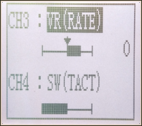 The channel 3 and channel 4 servo position can be set from the transmitter. When CH3 is assigned to the 3rd channel key, this setting is linked to the key. When CH3 and CH4 is not assigned to the 3rd channel key, it can be set with this screen.
You can also set the CH3 and CH4 as VR at the same time, or SW.
Channel 3 position (POSI)
SW(LOCK) or VR(RATE)
Channel 4 position (POSI)
SW(LOCK) or VR(RATE)
(1) Enter the function menu and use “Dec(-)” or “Inc(+)” button to access AUX function.
(2) Press “Enter” button to get into CH3 or CH4 function interface.
(3) Use “Dec(-)” or “Inc(+)” button to select Channel setup item.
Use “Dec(-)” or “Inc(+)” button to select POSI, press“Enter”key and the value will blink, use “Dec(-)” or “Inc(+)” button to select “VR” or “SW”.
Press “Enter” button, the adjusted value stops blinking, now the value has been set.
4.18 Model Name "NAME"
RC4GS stores model memories for ten models. Each model memory can be named separately according to user’s requirement.
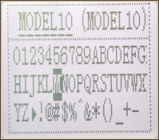 Factory default name: MODEL1
(1) Enter the function menu and use “Dec(-)” or “Inc(+)” button to access NAME function.
(2) Press “Enter” button to get into NAME function interface, the first character of current name will blink, and the blinking character can be reset. The common use characters appear at the bottom of the screen, use “Dec(-)” or “Inc(+)” button to choose the character you desired.Press“Enter” button again, the next character of current name will blink. Reset other characters of current name in same manner.
(3) After accomplishment of naming, all characters of current name will stop blinking, the new name will be stored automatically.
(4) When ending setting,return to the initial screen by pressing“Exit”button twice.(the new setting model name will appear on the initial screen)
4.19 Low Voltage Alarm
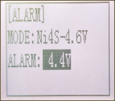 The transmitter’s low voltage alarm adjustable, it depends on what kind of battery, the 4.6V is may cause the battery over discharge and damage the battery. So you can set transmitter’s warning voltage when you use different battery.
There are four options you can choose:
Li2S-7.2V
Li3-10.8V
Ni4S-4.6V
ALARM: adjustable 4.0V to 16.0V
The car will be out of control if the battery runs out, please immediately stop running when the alarm starting to ring.
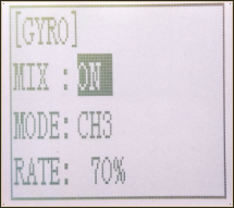
4.20 Gyro Sensitivity
This function is available to set gyro sensitivity and VR mixing ON or OFF.
When MIX set OFF, gyro is disabled while when MIX set ON, you can adjust gyro sensitivity STD or CH3. STD is adjusted on screen and CH3 can be adjusted by VR button. CH3 is defaulted by VR switch.
In normal mode (STD), range of sensitivity is 0%-100%.
(1) Enter the menu, use Dec(-) and Inc(+) to select options for gyro sensitivity.
(2) Press the key button “Enter” to enter sub-menu gyro sensitivity.
(3) Press “Enter” again, the initial value will start flashing, then use Dec (-) and Inc (+) to change the value.
(4) Press the button key “Enter”, the value stops flashing, the setting is finished now.
(5) "Mode"and "Rate" can also be set by the same step.
(6) Press button key “Exit” to be back to initial screen.
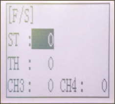
4.23 Fail Safe
This function is set by servo, throttle, CH3 and CH4.
 Option:
SERVO
THROTTLE
CH3
CH4
RANGE:
Servo: -100~+100
Throttle: -100~+100
CH3: -100~+100
CH4: -100~+100
Initial value: 0
(1) Enter the menu, use “Dec (-)” and “Inc (+)” to select options to set.
(2) Press the button key “Enter” to enter menu.
(3) Use “Dec (-)” and “Inc (+)” to select SERVO, then press “Enter”. Now the initial value
of SERVO will start flashing, use handle to change the value.
(4) Press the button key “Enter”, the value stops flashing, now the value of SERVO is set.
(5) THROTTLE is to set by the trigger.
CH3 is to set by VR controller.
CH4 is to set by the button switch.
(6) Press “Exit” two times to back to initial screen.
4.24 Reset Function "RESET"
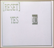 REST- Data reset function:
All the data for any model memory can be reset to original factory defaults. Often this function is done to get a “fresh start” and clear the memory before inputting new model settings.
(1) Enter the function menu and use “Dec(-)” or “Inc(+)” button to access RESET function.
(2) Press “Enter” button to get into RESET function interface, the symbol “YES” will blink.
Be sure to reset
Press “Enter” key, the symbol “YES” will stop blinking, and return to the initial screen. Now the model data is reset to the initial setting that is the default value set at the factory.
Not to reset
Press “Dec(-)” or “Inc(+)” button, the symbol “YES” will stop blinking and the symbol “NO” will blink, press “Enter” key, the symbol “NO” will stop blinking, return to the initial screen by pressing “Exit” button twice.
Or you can press “Exit” button twice to quit resetting directly.
CAUTION: Resetting the current model memory will permanently erase ALL programming information for that model. The data cannot be recovered. Do not reset the model unless you are certain you want to clear-out that memory and start from scratch.
Thank you again for using our product, we hope it can bring you happiness!