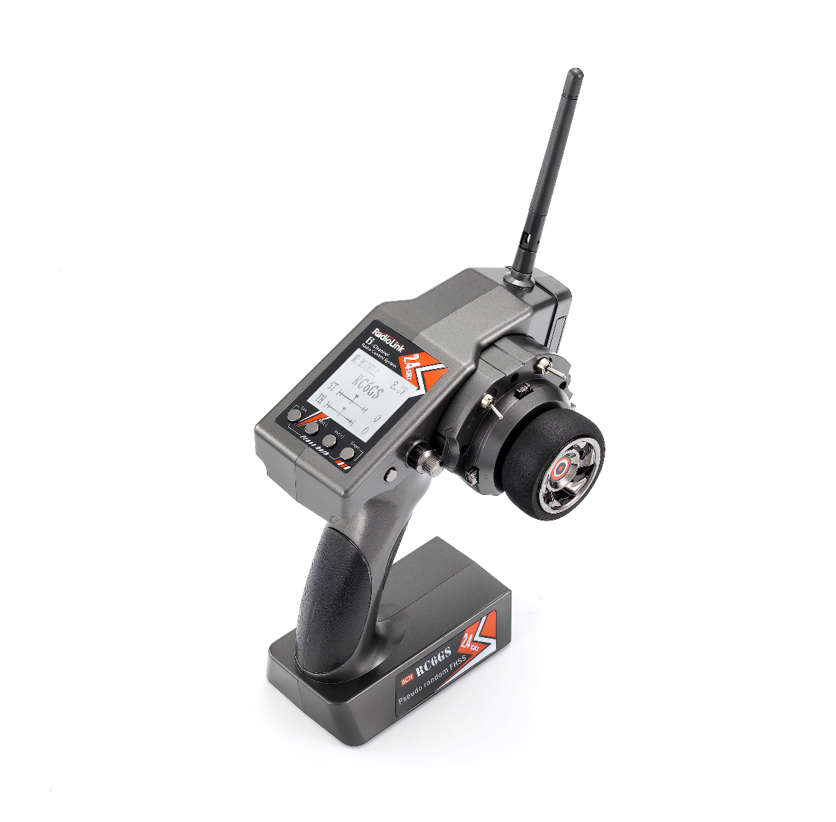
RC6GS
Digital 6-Channel Proportional RC System
Instruction Manual
Adaptable to RC Cars/Boats/Robots
CE FCC RoHS
* Please be kindly noted that this manual will be updated regularly and please visit RadioLink official website to download the latest version.
Thank you for choosing Radiolink 2.4 GHz 6 channels pistol grip radio -- RC6GS.
To fully enjoy the benefits of this product and ensure safety, please read the manual carefully and set up the device as instructed steps.
If any problems found during the operation process, either way listed below can be used as online tech support.
Send mails to or and we will answer your question at the earliest.
Private message us on our Facebook page or leave comments on our YouTube page
If the product is purchased from online store, you can contact after-sales service directly.
If the product is purchased from the local distributor, you can also ask them for support and repair as prefer.
All manuals and firmwares are available on RadioLink official website and more tutorials are uploaded. Or follow our Facebook and YouTube homepage to stay tuned with our latest news.
RC6GS User Manual Radiolink Facebook Radiolink YouTube
SAFETY PRECAUTIONS
Never operate your model during adverse weather conditions. Poor visibility can cause disorientation and loss of control of your model.
Never use this product in a crowd and illegal area.
Always ensure the trim levers at 0 and battery properly charged before connecting the receiver.
Always check all servos and their connections prior to each run.
Always be sure about turning off the receiver before the transmitter.
WARNING
This product is not a toy and is NOT suitable for children under the age of 14. Adults should keep the product out of the reach of children and exercise caution when operating this product in the presence of children.
Water or moisture may enter the transmitter inside through gaps in the antenna or joystick and cause model instability, even out of control. If running in the wet weather(such as game) is inevitable, always use plastic bags or waterproof cloth to cover the transmitter.
FCC Statement
This device complies with part 15 of the FCC Rules. Operation is subject to the following two conditions:
This device may not cause harmful interference, and Prevents external wireless interference, including interference that may cause undesired operation.
Any Changes or modifications not expressly approved by the party responsible for compliance could void the user's authority to operate the equipment.
Packing list
| No. | Items | Qty |
| 1 | TX RC6GS | 1 |
| 2 | RX R7FG | 1 |
| 3 | Wire for Model Voltage Return | 1 |
| 4 | Instruction Manual | 1 |
CONTENTS
I. 1
1.1 1
1.2 Receiver 2
1.2.1 Receiver Installation and Binding 2
1.2.2 Working Mode 3
1.2.3 How to Turn On Gyro Function 4
1.2.4 Signal/RSSI Real-time Return 5
1.2.5 Return of model battery and receiver voltage 5
II. RC6GS Functions 6
2.1 Display When Power Switch Turned On 6
2.2 Language Select "LANGUAGE" 7
2.3 Model Select "MODEL" 7
2.4 End Point Adjuster "EPA" 7
2.5 Steering EXP "STEXP" 8
2.6 Steering Speed "STSPD" 9
2.7 Throttle EXP "THEXP" 9
2.8 Throttle Speed "THSPD" 11
2.9 A.B.S. Function "A.B.S" 12
2.10 Throttle Acceleration "ACCEL" 15
2.11 Idle-Up "IDLUP" 16
2.12 Sub-trim "SUBTR" 16
2.13 Servo Reverse "REV" 17
2.14 Steering Dual Rate/Throttle Dual Rate "D/R" 17
2.15 ATL Function "ATL" 18
2.16 Programmable Mixes "PMIX" 18
2.17 Channel 3 Position "AUX" 23
2.18 Model Name "NAME" 24
2.19 Low Voltage Alarm 25
2.20 Gyro Sensitivity 25
2.21 Fail Safe 25
2.22 ID SEED 26
2.23 RESET 26
Pistol Grip Control System
RC6GS, transmitter with chip STM32F103RB, receiver R7FG with 32 bits industrial chip, 12ms only from transmitter to the receiver, thus provide synchronous control and perfect performance .
The same FHSS spread spectrum and 67channels pseudo random frequency sequence hopping of AT9S makes RC6GS have superior anti-interference ability both at the same frequency band and different frequency bands.
Control distance is up to 600 meters.
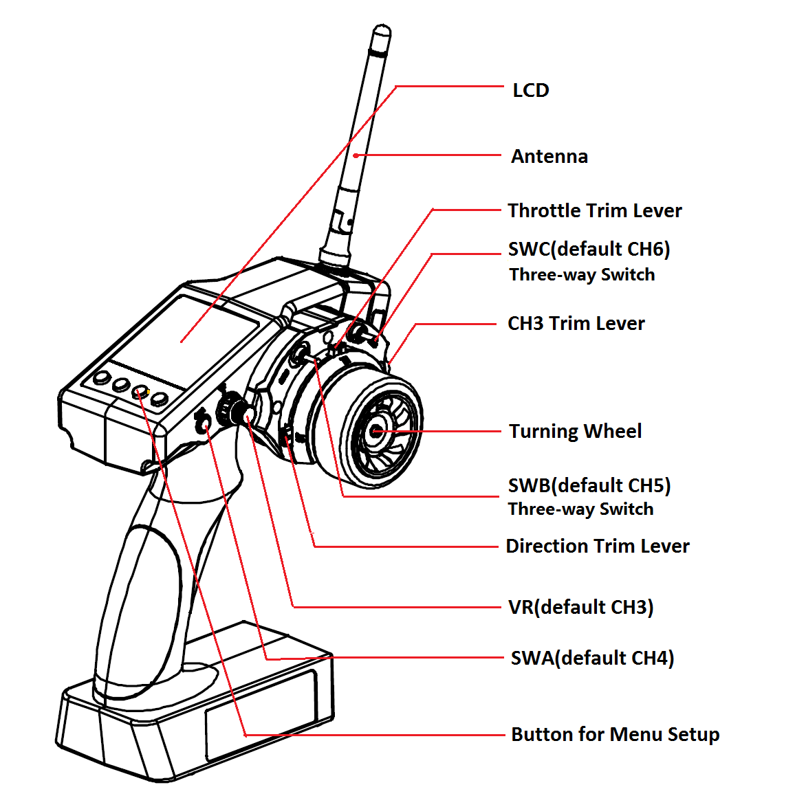
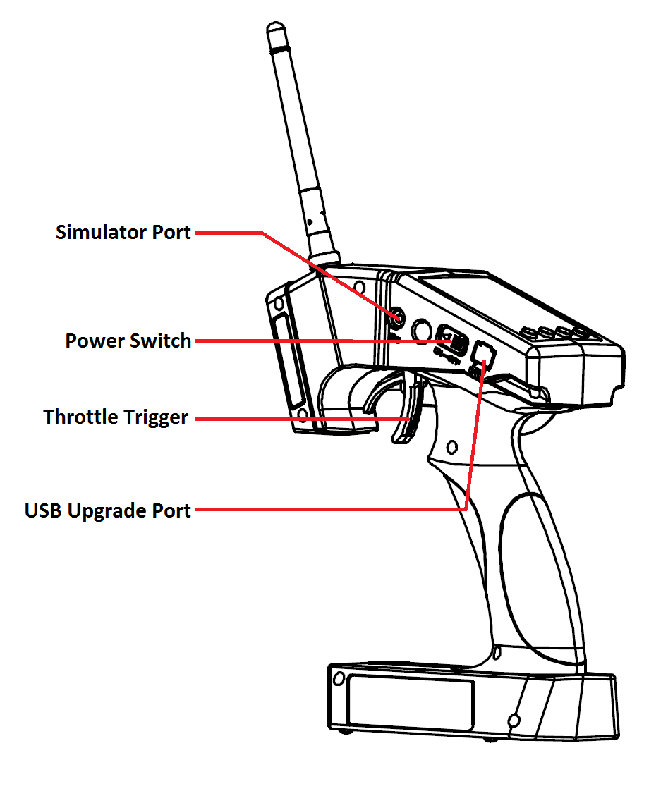
1.1 Transmitter
Size: 213 *117 * 115.5mm
Frequency: 2.4Ghz ISM Band(2400MHZ-2483.5MHz)
Channel: 6 CH
Channel resolution: 4096, the regular jitter is 0.5us
Model: Cars/Boats
Modulation Mode: GFSK
Spread Spectrum: FHSS, 67 Channels Pseudo Random Frequency Sequence Hopping
10 Modes Memory Storage
Antenna Length: 106mm
Control Distance: More than 600 meters on ground
LCD Screen: 128*64 Resolution, LCD Back Light
Transmitter Operating Voltage: 4.8-15.0V DC
Transmitter Battery: 6*AA or 2-4S lithium battery
Transmitter operating current : 80-120mA
RF power: <20dbm
Low Voltage alert: Yes(lower than 4.6V), can be set when using 2-4S LiPo battery
Compatible Receiver: R7FG, R6FG, R6F, R8EF, R8FM, R8F, R4FGM
1.2 Receiver
RC6GS, sells with R7FG, 2.4GHz 7 channels receiver, gyro integrated and HV servo supported.
Specification
Frequency: 2.4GHz ISM band (2400MHz~2483.5MHz)
Size: 35*20*13mm
Channel: 7
Model: cars/boats
Modulation mode: GFSK
Spread spectrum: FHSS
Antenna length: 200mm
Control distance: more than 600 meters
Power supply: 4.6~10.0V DC
Channel resolution: 4096, the regular jitter is 0.5us
Work current: 30mA
1.2.1 Receiver Installation and Binding
How to bind receiver to transmitter:
1. Put the transmitter and the receiver close to each other within 30-50 centimeters.
2. Power on RC6GS transmitter and receiver R7FG, the LED of R7FG will start flashing slowly.
3. Turn on RC6GS and it will automatically bind with the closest receiver.
4.Press the ID SET on the R7FG receiver’s side for more than 1s and the GREEN indicator will flash, meaning the binding process has begun.
5. When the GREEN LED stops flashing and is always on , binding is complete.
6.Make sure servos connected with the receiver can be operated by the transmitter.
1.2.2 Working Mode
R7FG has four working modes:
| R7FG Working Mode | |||||
| Working Mode | Mode 1 | Mode 2 | Mode 3 | Mode 4 | Note |
| Indicator Color | Green | Blue | Red&Blue(Purple) | Red&Green(Orange) | / |
| With Gyro | N | N | Y | Y | Multicolor light indicator on means gyro function on |
| Channel | Corresponding signal output in different channel | ||||
| BAT+- | Return port of model battery voltage | ||||
| 1 | PWM | PWM | PWM | PWM | Rudder |
| 2 | PWM | PWM | PWM | PWM | Throttle |
| 3 | PWM | PWM | PWM | PWM | Aux |
| 4 | PWM | PWM | PWM | PWM | Aux |
| 5 | PWM | PWM | PWM | PWM | Aux |
| 6 | PWM | PWM | PWM | PWM | Aux |
| PPM/S.B | PPM | SBUS | SBUS | PPM | Green is PPM, Blue is S-BUS, flight controller can be connected under SBUS/PPM mode and achieve different models control incl. Mecanum car/Robot/Engineering Off-road cars |
| Signal Switch | Short press ID set once to Mode 2 | Short press ID set once to Mode 1 | Short press ID set once to Mode 4 | Short press ID set once to Mode 3 | / |
| Short press ID set 3 times quickly to Mode 4 | Short press ID set 3 times quickly to Mode 3 | Short press ID set 3 times quickly to Mode 2 | Short press ID set 3 times quickly to Mode 1 | / | |
Mode 1: PWM+PPM output ( factory setting by default, NO gyro)
When the Green indicator is on, Channel 1 to Channel 6 output standard PWM while Channel 7 outputs PPM. Short press ID SET once to change Mode 1 to Mode 2 and three times within 1 second to Mode 4.
Mode 2: PWM+SBUS output (NO gyro)
When the Blue indicator is on, Channel 1 to Channel 6 output standard PWM while Channel 7 outputs SBUS. Short press ID SET once to change Mode 2 to Mode 1 and three times within 1 second to Mode 3.
Mode 3: PWM+SBUS output+ Gyro
When both the Red and the Blue indicators are on (Purple), Channel 1 to Channel 6 output standard PWM while Channel 7 outputs SBUS. Meanwhile, the Gyro function is also on, stabilizing the direction, keeping car from slipping and ensuring safer turning to preventing drifting from fast speed.
Short press ID SET once to change Mode 3 to Mode 4 and three times within 1 second to Mode 2.
Mode 4: PWM+PPM output+Gyro
When both the Red and the Green indicators are on (Orange), Channel 1 to Channel 6 output standard PWM while Channel 7 outputs PPM. Meanwhile, gyro function is also on, stabilizing the direction, keeping car from slipping and ensuring safer turning to preventing drifting from fast speed.
Short press ID SET once to change Mode 4 to Mode 3 and three times within 1 second to Mode 1.
1.2.3 How to Turn On Gyro Function
Factory setting is gyro function OFF by default. Since integrated gyro in R7FG will self-check, it is very important to remain R7FG still when powering it on. There are four colors LED indicators on R7FG with four working mode. GREEN and BLUE LEDs indicate Gyro function is turn off. GREEN+RED LEDs (Orange) and RED+BLUE LEDs (Purple) indicate gyro turn on. Please refer above mention to check.
Gyro Phase
Only the phase is correctly set that the gyro can always revise directions.
When the gyro forward is enabled, try to turn the model car to check if the gyro is correcting the wheels. Normally, the wheels should turn right to correct when the car is turned left while the wheels should turn left to correct when the car is turned right. If the gyro phase is reversed, short press the binding button (ID SET) twice in 1 second. The Red indicator flashes twice means the gyro phase setting is complete.
Transmitter Sensitivity Adjustment
Gyro sensitivity can be adjusted by STD or CH3 in GYRO menu. VR rotary switch is CH3 by default (factory setting). Percentage is displayed when sensitivity is adjusted while the bigger percentage means higher sensitivity. When rotated clockwise, sensitivity increased and anticlockwise means decreased. If the VR rotary switch/CH3 is set with other function, menu setting on transmitter can be used to adjust gyro sensitivity.
Note of receiver usage
Keep the two antennas at a 90-degree angle (as shown below):
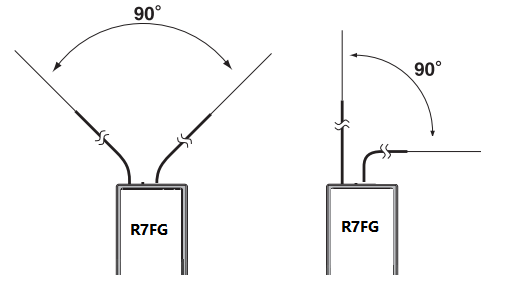
Big models may contain metal parts that influence signal emission. In this case, antennas should be positioned at both sides of the model to ensure the best signal status in all circumstances.
Antennas should be kept away from metal conductor and carbon fiber at least half inch away and no over bending.
Keep antennas away from motor, ESC or other possible interference sources.
Sponge or foam material is advised to use to prevent vibration when installing receiver.
Receiver contains some electronic components of high-precision. Be careful to avoid strong vibration and high temperature.
Special vibration-proof material for R/C like foam or rubber cloth is used to pack to protect receiver. Keeping the receiver in a well sealed plastic bag can avoid humidity and dust, which would possibly make the receiver out of control.
When all the above steps are complete, please turn off the transmitter and re-power on to test if the receiver is correctly connected with it.
1.2.4 Signal/RSSI Real-time Return
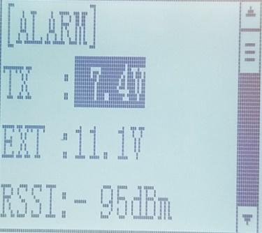
Power on the transmitter and the receiver and complete the binding, signal will be displayed on the main interface of transmitter. Short press EXIT twice and enter the interface with returned information including RSSI value.
Warning can be set with a certain low RSSI value after testing by changing distance:
Press EXIT and ENTER simultaneously to enter MENU=>press Inc(+) to highlight “ALARM” =>Press ENTER to (dis)activate the warning and set the RSSI warning value.
1.2.5 Return of Model Battery and Receiver Voltage
Only when the RC6GS is the 3-way switch version and updated with the latest version of V6.0.0 or above that can make binding with R7FG/R8F. Besides the return of RSSI, receiver voltage, model battery voltage (maximun up to 6S lithium battery) can also be returned in real time. Users can personalize the warning value of low model battery voltage depending on the actual needs.
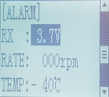
Note: The 'RATE: RPM' and 'T: NULL' telemetry functions are still under development. If there are new developments, we will announce them to the Radiolink official website as soon as possible, thanks for your attention.
Press EXIT and ENTER simultaneously to enter MENU=>press Inc(+) to highlight “ALARM =>Press ENTER to set the model battery voltage warning value.
Normally we set the warning value with the single cell voltage as 3.7V. For example, if it is 3S lithium battery used in the model car, the warning value should be set as (3.7V*3S=)11.1V.
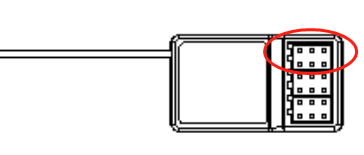
Model battery voltage return can be easily achieved by connecting the male end of the battery wire to ESC while the female end to the battery and the wire with a JST head connects BAT (+-) of R7FG/R8F as below pic shown. No extra module is needed.
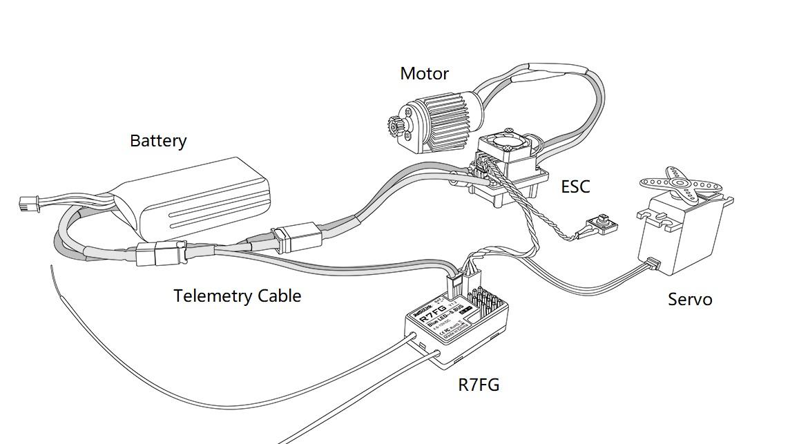
Once connect with success, the returned model voltage will be displayed on the interface of returned flight information.
II. RC6GS Functions
2.1 Display When Power Switch Turned On
When you power on the transmitter RC6GS, LCD screen shows Model Name, Transmitter Name, Transmitter Voltage, Steering Trim, Throttle Trim, Model Voltage, Subsidiary Model ID, Returned Signal.
Model Name
The system can store the data for 10 models, model name will show on the LCD when you power on the transmitter. Please make sure the model name is the right one that you want.
If the model name you chose is not corresponding with your model, the settings should be wrong.
Transmitter Voltage
In addition to the model, LCD can show the voltage of battery. When the voltage is lower than 4.6V, it would start the low-voltage alarm, it would send out “DDD…” sounds, till the transmitter is power-off. When you hear the low-voltage alert, you have no more than 4 minutes for controlling your model, please safely stop your model before the uncontrolled situation. Please make sure the battery voltage is higher than this voltage data while radio controlling.
 Transmitter function menu setting
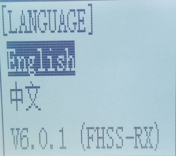
2.2 Language Select "LANGUAGE"
Both English and Chinese version menu are available for which is convenient for Chinese and English-speaking players to personalize function menus.
(1) Access the function menu (By pressing “Exit” and “Enter”buttons simultaneously and holding them down for one second), the Language select function will be chosen.
(2) Press “Enter” button to get into “LANGUAGE” function interface.
(3) Use“Dec(-)”or “Inc(+)”key to select “中文”or “English”, the selected language will be with black shading effect.
(4) Press “Enter” button, the desired language is selected, and return to the initial screen automatically.
2.3 Model Select "MODEL"
RC6GS can store model memories for ten models. Use this function to call a new model.
(1) Access the function menu (By pressing “Exit” and“Enter” buttons simultaneously and holding them down for one second), press “Enter” key once, the Model select function will be chosen.
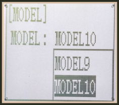 (2) Press “Enter” button, the current active model will be blinking.
(3) To activate a different model by pressing “Dec(-)” or “Inc(+)” button until the desired model blinks.
(4) Press “Enter” button, the selected model stops blinking, now the model has been selected.
(5) Return to the initial screen by pressing “Exit” button twice.
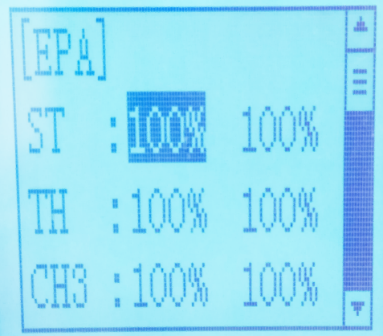
2.4 End Point Adjuster "EPA"
Use EPA when performing left and right steering angle adjustments, throttle high side/brake side operation amount adjustment, and channel 3 servo up side/down side operation amount adjustment during linkage.
 Correct the maximum steering angle and left and right steering angles when there is a difference in the turning radius due to the characteristics, etc. of the vehicle.
Setting item (channel and direction)
ST :Steering (left/right)
TH: Throttle (forward/brake)
CH3: 3rd channel (left/ right)
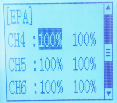
CH4: 4th channel (left/ right)
CH5: 5th channel (left/ right)
CH6: 6th channel (left/ right)
Steering EPA Throttle EPA
 ST:0%~120%(left/ right) TH:0%~120%(forward/brake)
Initial value:100% Initial value : 100%
Aux Servo EPA Aux Servo EPA
CH3:0%~120%(left/ right) CH4:0%~120%(left/ right)
Initial value: 100% Initial value: 100%
Aux Servo EPA Aux Servo EPA
CH5:0%~120%(left/ right) CH6:0%~120%(left/ right)
Initial value: 100% Initial value: 100%
End Point Adjustment
1.Access the function menu (By pressing “Exit” and “Enter” buttons simultaneously and holding them down for one second),press “Inc(+)” button twice to chose EAP function.
2.Press “Enter” button to get into EPA function interface, use “Dec(-)” or “Inc(+)” button to select the desired setting item , press “Enter” key, the initial value of your selected setting item will blink, then you can press “Dec(-)” or “Inc(+)” button to adjust the value of your selected setting item.
(Note: In the interface of adjusting the value, return to the initial value "100%" by pressing “Dec(-)” and “Inc(+)” buttons simultaneously for about 1 second.)
3. Press “Enter” button, the adjusted value of your selected setting item stops blinking, now the value of your selected setting item has been set.
Return to the initial screen by pressing “Exit” button twice.
2.5 Steering EXP "STEXP"
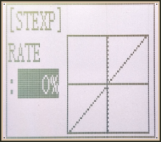 This function is used to change the sensitivity of the steering
servo around the neutral and both ends position. It has no effect
on the maximum servo travel.
Adjust the sensitivity of direction wheel both in neutral position and ends.
Setup Item
RATE: Steering EXP rate
Adjustment range
-100%~0%~+100%
Initial value: 0%
0%~-100%: Sensitivity around neutral position is low, getting higher when approaching ends.
0%: Sensitivity around the neutral and ends position is equal
0%~+100%: Sensitivity around neutral position is high, getting lower when approaching ends
Steering operation curve adjustment
(1) Access the function menu (By pressing “Exit” and “Enter ”buttons simultaneously and holding them down for one second ), press “Inc(+)” button three times to chose EAP function.
(2) Press “Enter” button to get into STEXP function interface, press “Enter”key and the initial value of the rate will blink, then you can press “Dec(-) ”or “Inc(+)”button to adjust the value and the curve of the rate shown in the figure will change correspondingly.
(Note: In the interface of adjusting the value, return to the initial value "0%" by pressing “Dec(-)” and“Inc(+)” buttons simultaneously for about 1 second.)
(3) Press “Enter” button, the adjusted value of the rate stops blinking, now the value of the rate has been set.
(4) Return to the initial screen by pressing“Exit” button twice.
Note: the Vertical cursor shown in the figure moves in step with steering wheel operation.
2.6 Steering Speed "STSPD"
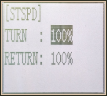 Quick steering operation will cause momentary under steering, loss of speed, or spinning. This function is effective in such cases.
Setup item
TURN: turn direction
RETURN: return back to the original direction
Adjustment range
0%~100% (each direction)
At 100%, there is no delay
Steering servo delay
(1) Access the function menu (By pressing “Exit” and “Enter” buttons simultaneously and holding them down for one second), press “Inc(+)” button four times to chose STSPD function.
(2) Press“Enter” button to get into STSPD function interface, press “Dec(-)” or“Inc(+)” button to select setup item, then press “Enter” key and the initial value of selected setup item will blink.
(3) Use“Dec(-)” or “Inc(+)” button to adjust the value of the selected setup item.
(Note : In the interface of adjusting the value, return to the initial value "100%" by pressing“Dec(-)” and“Inc(+)” buttons simultaneously for about 1 second.)
(4) Press “Enter”button, the adjusted value of the selected setup item stops blinking, now the value of the selected setup item has been set.
(5) Return to the initial screen by pressing “Exit” button twice.
2.7 Throttle EXP "THEXP"
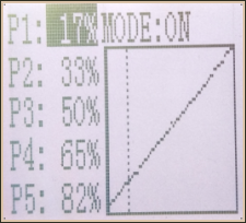
This function makes the throttle high side and brake side direction servo operation quicker or milder. It has no effect on the servo maximum operation amount. For the high side, selection from among three kinds of curves (CRV/VTR/EXP) is also possible.
The curve can be divided into: Five dots throttle curve adjustment, Single point adjustment,
Exponential curve adjustment, Braking index curve adjustment. To elevation point,
we can select(Exponential curve/Single point curve/Five points curve).
Curve point adjustment(select five points 1-5)
 (1) Press"Enter" button,The curve point value start flashing,then press"Dec(-)"and"Inc(+)" button to adjust the starting value.
(2) Press "Enter" button ,starting value stop flashing,adjustment is completed.
(3) Press "Exit" button for two times,back to the initial interface.
Throttle curve adjustment
Adjustment method for CRV curve
Setup Items
Mode: ON/OFF
RATE: 0%~100%
Enter the function menu and use“ Dec(-) ” or “ Inc(+) ”button
to access THEXP function. Select “FWD-CRV” function.
2. Press “Dec(-)” or “Inc(+)” button to select curve points 1~5 for curve point adjustment that you want, from the graph you will clearly see the changes you have made.
Adjustment method for VTR curve
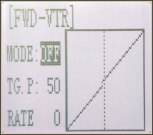 Adjustment range
TG.P: 20-80
RATE: -100~0~+100
Enter the function menu and use “Dec(-)” or“Inc(+)”button to access THEXP function. Select“FWD-VTR” function.
Press “Dec(-)” or “Inc(+)” button to select RATE for forward side adjustment that you want, when the “MODE” value is “OFF” the VTR will not work, only the “MODE” value set to “ON” the VTR function is available. From the graph you will clearly see the changes you have made on TG.P and RATE.
Adjustment method for EXP curve
Setup items
MODE: EXP turn on or turn off
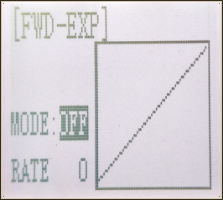 RATE: EXP rate
Adjustment range
MODEL: OFF/ON
RATE: -100 ~ 0 ~ +100
Enter the function menu and use “Dec(-)” or “Inc(+)” button
to access THEXP function, then select the “FWD-EXP” function.
2. Press “Dec(-)” or “Inc(+)” button to select RATE for adjustment, set the most comfortable value you want. From the graph you will clearly see the changes you have made on the EXP RATE, also move the trigger to check the throttle status.
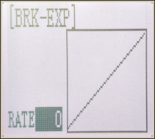 Adjustment method for BRK-EXP curve
Setup Items
RATE: BRK-EXP rate
Adjustment range
RATE: -100 ~ 0 ~ +100
0~-100: flat braking
0: uniform braking
0~+100: sensitive braking
Brake side adjustment (select BRK)
Press “Enter” key, the current BRK value will blink, use “Inc(+)” button to adjust the + side when you want to quicker the rise and use“Dec(-)” button to adjust the - side when you want to make the rise milder.
(Note: In the interface of adjusting the value, return to the initial value "0" by pressing “Dec(-)” and “Inc(+)” buttons simultaneously for about 1 second.)
Press “Enter” button, the adjusted BRK value stops blinking, now the BRK value has been set.
When ending setting, return to the initial screen by pressing “Exit” button twice.
2.8 Throttle Speed "THSPD"
 Throttle servo delay
Sudden trigger operation on a slippery road only causes the wheels to spin and the vehicle cannot accelerate smoothly. Setting the throttle speed function reduces wasteful battery consumption while at the same time permitting smooth, enjoyable operation.
Operation
Throttle servo(amp )operation is delayed so that the drive wheels will not spin even if the throttle trigger is operated more than necessary. This delay function is not performed when the throttle trigger is returned and at brake operation.
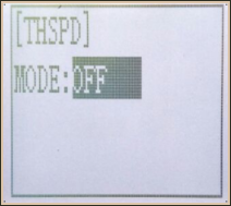
 OFF: Speed1 or speed2 can be selected.
OFF means shut down the throttle speed function
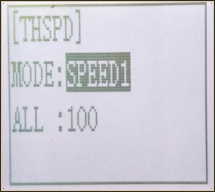
Adjustment method for SPEED1
Setup items
MODE: Speed type selection
ALL: Speed adjustment
Adjustment range
0~100 (each direction)
At 100, there is no delay
(1) Enter the function menu and use “Dec(-)”or“Inc(+) ” button to access THSPD function.
(2) Press “Enter” button to get into THSPD function interface.
(3) If initial MODE setup item is SPEED1, {if initial MODE setup item is SPEED2 or OFF, you need to select SPEED1 by pressing“Dec(-)” or “Inc(+)”button to select MODE setup item , then press “Enter” key, SPEED2 or OFF will blink, press “Dec(-)” or “Inc(+)” button, when the blinking SPEED 2 or OFF change to blinking SPEED 1, press “Enter” key, SPEED1 will stop blink, now SPEED1 is selected}, press “Dec(-)” or “Inc(+)” button to select ALL setup item, then press“Enter” key, the initial value will blink, use“Dec(-)”or“Inc(+)” button to adjust the delay of the entire throttle forward side range.
(Note: In the interface of adjusting the value, return to the initial value "100" by pressing “Dec(-)” and “Inc(+)” buttons simultaneously for about 1 second.)
Press “Enter” button, the adjusted value stops blinking, now the value has been set.
When ending setting, return to the initial screen by pressing “Exit” button twice.
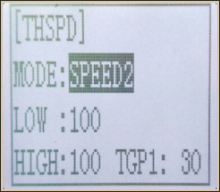 Adjustment method for SPEED2
Setup items
MODE: Speed type selection
LOW: Low side range speed adjustment
HIGH: High side range speed adjustment
TGP1: Low and medium speed switching point
Adjustment range
LOW: 0~100
HIGH: 0~100
At 100, there is no delay
TGP1: 0~100
(1) Enter the function menu and use “Dec(-)”or “Inc(+) ” button to access THSPD function.
(2) Press “Enter” button to get into THSPD function interface.
(3) If initial MODE setup item is SPEED 2,{ if initial MODE setup item is SPEED 1, you need to select SPEED2 by pressing “Dec(-)” or “Inc(+)” button to select MODE setup item, then press “Enter” key, SPEED1 or OFF will blink, press “Dec(-)” or “Inc(+)” button, when the blinking SPEED1 or OFF change to blinking SPEED2, press “Enter” key, SPEED2 will stop blinking, now SPEED2 is selected}, press “Dec(-)” or “Inc(+)” button to select "LOW" or "HIGH" delay adjustment or“TGP1” speed switching point adjustment.
(4) Press “Enter” key to confirm "LOW" or "HIGH" or “TGP1” setup item, and the value of your selected setup item will blink. Use “Dec(-)” or “Inc(+)” button to adjust the value.
(Note: In the interface of adjusting the value, return to the initial value (the initial value of LOW and HIGH is “100”, the initial value of TGP1 is “30”) by pressing “Dec(-)” and “Inc(+)” buttons simultaneously for about 1 second.)
Press “Enter” button, the adjusted value stops blinking, now your selected value has been set.
(5) When ending setting, return to the initial screen by pressing “Exit” button twice.
2.9 A.B.S. Function "A.B.S"
Pulse brake
When the brakes are applied while cornering with a 4 Wheel Drive or other type of vehicle, under-steer may occur. The generation of under-steer can be eliminated and corners can be smoothly cleared by using this function.
Operation
- When the brakes are applied, the throttle servo will pulse intermittently. This will have the same effect as pumping the brakes in a full size car.
- The brake return amount, pulse cycle, and brake duty can be adjusted.
- The region over which the ABS is effective can be set ac-cording to the steering operation. (Mixing function)
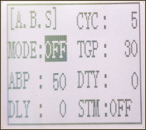
Setup items
ABP: Brake return amount
DLY: Delay amount
CYC: Cycle speed
TGP: Operation point
DTY: Cycle duty ratio
STM: Steering mixing
-ABP(Amount of brake return): Sets the rate at which the servo returns versus trigger operation for brake release. When set to 0, the ABS function is not
Performed. When set to 50, the servo returns 50% (1/2)of the trigger operation amount and when set to 100, the servo returns to the neutral position.
-DLY(Delay): Sets the delay from brake operation to ABS operation. When set to 0, the ABS function is
activated without any delay. At 50%, the ABS function is activated after a delay of approximately 0.7 second and at 100, the ABS function is activated after a delay of approximately 1.4 seconds.
-CYC(Pulse speed): Sets the pulse speed (cycle). The smaller the set value, the faster the pulse cycle.
- TGP(Trigger point): Sets the trigger point at which the ABS function begins to operate at brake operation.
-DTY(Cycle duty ratio): Sets the proportion of the time the brakes are applied and the time the brakes are released by pulse operation. The ratio can be set to +3 ~ 0~-3 in 7steps.
- STM(Steering mixing): Sets ABS operation ON/OFF according to the steering operation range.
A.B.S function adjustment
Enter the function menu and use “Dec(-)” or “Inc(+)” button to access A.B.S function, then press“Enter” button to get into A.B.S function interface.
(1) Brake return amount adjustment
Select the setting item "ABP" by pressing “Dec(-)” or “Inc(+)” button, then press “Enter” key and the initial value of “ABP” will blink. Use “Dec(-)”or“Inc(+)”button to adjust the return amount.
(Note: In the interface of adjusting the value, return to the initial value "50" by pressing “Dec(-)” and “Inc(+)” buttons simultaneously for about 1 second.)
Press “Enter” button, the adjusted value stops blinking, now the value has been set.
"0": No return
"50": Return to the 50% position of the brake operation amount
"100": Return to the neutral position.
Brake return amount (ABP)
0 ~ 50 ~ 100
Initial value: 50
- Brake return amount (ABP) is influenced by the "EXP" rate on the brake side.
(2) Delay amount setup
Select the setting item "DLY" by pressing “Dec(-)” or “Inc(+)” button, then press “Enter” key and the initial value of “DLY” will blink. Use “Dec(-)”or “Inc(+)”button to adjust the delay amount.
(Note: In the interface of adjusting the value, return to the initial value "0" by pressing “Dec(-)” and “Inc(+)” buttons simultaneously for about 1 second.)
Press “Enter” button, the adjusted value stops blinking, now the value has been set.
"0": A.B.S. function performed without any delay
"50": A.B.S function performed after an approximate 0.7 sec delay
"100": A.B.S. function performed after an approximate 1.7 secs delay
Delay amount (DLY)
0 ~ 100
Initial value; 0
(3) Pulse speed adjustment
Select setting item "CYC" by pressing “Dec(-)” or “Inc(+)” button, then press “Enter” key and the initial value of “CYC” will blink. Use “Dec(-)” or “Inc(+)”button to adjust the pulse speed (cycle).
(Note: In the interface of adjusting the value, return to the initial value "5" by pressing“Dec(-)” and “Inc(+)” buttons simultaneously for about 1 second.)
Press “Enter” button, the adjusted value stops blinking, now the value has been set.
- The smaller the set value, the faster the pulse speed.
Cycle speed (CYC)
0 ~ 30
Initial value: 5
(4) Operation point setup
Select setting item "TGP" by pressing “Dec(-)” or “Inc(+)” button, then press “Enter” key and the initial value of “TGP” will blink. Use “Dec(-)” or “Inc(+)”button to adjust the operation point.
(Note: In the interface of adjusting the value, return to the initial value "30" by pressing “Dec(-)” and “Inc(+)” buttons simultaneously for about 1 second.)
Press “Enter” button, the adjusted value stops blinking, now the value has been set.
- Sets the throttle trigger position at which the A.B.S. function is performed. The number is the 100 display with the full brake position made 100%.
Operation point (TGP)
0 ~ 100
Initial value: 30
(5) Cycle duty ratio setup
Select setting item "DTY" by pressing “Dec(-)” or “Inc(+)” button, then press“Enter” key and the initial value of “DTY” will blink. Use “Dec(-)” or “Inc(+)”button to adjust the duty ratio.
(Note: In the interface of adjusting the value, return to the initial value "0" by pressing “Dec(-)” and “Inc(+)” buttons simultaneously for about 1 second.)
Press “Enter” button, the adjusted value stops blinking, now the value has been set.
"-3": Brake application time becomes shortest. (Brakes lock with difficulty)
"+3": Brake application time becomes longest (Brakes lock easily)
(Remark) For low grip set at the - side and for high grip set at the + side.
Duty ratio (DTY)
-3 ~ 0 ~ +3
Initial value: 0
(6) Steering mixing setup
Select setting item "STM" by pressing“Dec(-)”or“Inc(+)”button, then press“Enter” key and the initial value of “STM”will blink. Use “Dec(-)”or “Inc(+)”button to adjust the steering mixing range.
(Note: In the interface of adjusting the value, return to the initial value "OFF" by pressing “Dec(-)” and “Inc(+)” buttons simultaneously for about 1 second.)
Press“Enter”button, the adjusted value stops blinking, now the value has been set.
-Sets the range within which the A.B.S. function is performed relative to steering wheel operation.
Steering mixing (STM)
OFF, N10 ~ N100, E10 ~ E100
Initial value: OFF
When steering mixing is set and steering operation enters the set range, "*" is displayed in front of the number. When mixing is OFF, the A.B.S function can operate over the entire steering range.
When ending setting, return to the initial screen by pressing “Exit” button twice.
2.10 Throttle Acceleration "ACCEL"
Function which adjusts the movement characteristic from the throttle neutral position.
The servo will jump to the input position at its maximum possible speed. Unlike exponential, which adjusts the whole throttle movement into a curve, throttle acceleration simply "jumps" away from neutral and then leaves the remaining response linear.
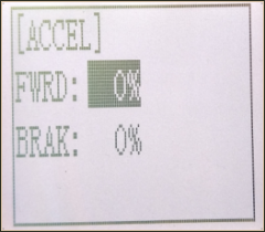
Setup item
FWRD: Forward side acceleration amount
BRAK: Brake side acceleration amount
Throttle acceleration adjustment
Enter the function menu and use “Dec(-)” or “Inc(+)” button to access ACCEL function, then press “Enter” button to get into ACCEL function interface.
(1) Forward acceleration amount adjustment
Press “Dec(-)” or “Inc(+)” button to select “FWRD”, press“Enter”key to confirm and the initial value of “FWRD” will blink, then use “Dec(-)”or“Inc(+)” button adjust the acceleration amount.
(Note: In the interface of adjusting the value, return to the initial value "0%" by pressing “Dec(-)” and “Inc(+)” buttons simultaneously for about 1 second.)
Press“Enter”button, the adjusted value stops blinking, now the value has been set.
"0%": No acceleration
"100%": Maximum acceleration(Approximately1/2of the forward side steering angle)
Forward acceleration amount(FWRD)
0%~100%
Initial value: 0%
(2) Brake side acceleration amount adjustment
Press “Dec(-)” or “Inc(+)” button to select “ BRAK ”, press“Enter”key to confirm and
the initial value of “BRAK” will blink, then use“Dec(-)”or“Inc(+)”button adjust the acceleration amount.
(Note: In the interface of adjusting the value, return to the initial value"0%" by pressing
“Dec(-)” and “Inc(+)” buttons simultaneously for about 1 second.)
Press “Enter” button, the adjusted value stops blinking, now the value has been set.
"0%": No acceleration
"100%": Maximum acceleration (Brake side maximum steering angle)
Brake side acceleration amount(BRAK)
0%~100%
Initial value: 0%
When ending setting, return to the initial screen by pressing “Exit” button twice.
2.11 Idle-Up "IDLUP"
Idle up at engine start
 Use this function to improve the starting characteristics of the engine by raising the idling speed when starting the engine of a gas powered car.
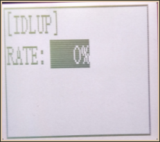
Idle-Up rate (RATE)
-50% ~ -1%, 0%, +1% ~ +50%
Initial value: 0%
"-": Brake side
"+": Forward side
Idle-Up "IDLUP"
(1) Enter the function menu and use “Dec(-)” or“Inc(+) ” button to access IDLUP function.
(2) Press “Enter” button to get into IDLUP function interface.
(3) Press “Enter” key, and the initial value of RATE will blink. Use“ Dec(-) ” or “Inc(+)” button to adjust the value.
(Note: In the interface of adjusting the value, return to the initial value "0%" by pressing “Dec(-)” and “Inc(+)” buttons simultaneously for about 1 second.)
Press “Enter”button, the adjusted value stops blinking, now the value has been set.
(4) When ending setting, return to the initial screen by pressing “Exit”button twice.
2.12 Sub-trim "SUBTR"
Servo center position adjustment
 Use this function to adjust the neutral position of the steering, throttle and channel 3 servos.
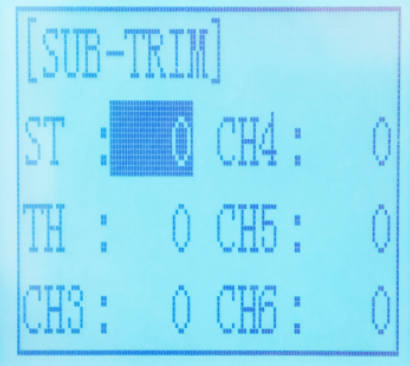
Channel
ST: Steering(CH1)
TH: Throttle(CH2)
CH3: Channel3(VR)
CH4: Channel4(SWA)
CH5: Channel5(SWB)
CH6: Channel6(SWC)
Sub-trim
ST: -100~0~+100
TH: -100~0~+100
CH3: -100~0~+100
CH4: -100~0~+100
CH5: -100~0~+100
CH6: -100~0~+100
Initial value : 0
(1) Enter the function menu and use “Dec(-)”or “Inc(+)” button to access SUBTR function.
(2) Press “Enter” button to get into SUBTR function interface.
(3) Use “Dec(-)” or “Inc(+)” button to select ST channel, press “Enter”key, and the initial value of ST will blink. Use “Dec(-)” or “Inc(+)” button to adjust the center.
(Note: In the interface of adjusting the value, return to the initial value "0" by pressing “Dec(-)” and “Inc(+)” buttons simultaneously for about 1 second.)
(4) Press “Enter” key, the adjusted value stops blinking, now the center of ST has been adjusted.
(5) TH channel and CH3 can be set similarly.
(6) When ending setting, return to the initial screen by pressing “Exit” button twice.
2.13 Servo Reverse "REV"
Servo operation reversing
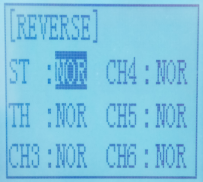 This function reverses the direction of operation of the servos related to transmitter steering, throttle, channel 3, channel 4, channel 5 and channel 6 operation.
Channel
ST: Steering(CH1)
TH: Throttle(CH2)
CH3: Channel3(VR)
CH4: Channel4(SWA)
CH5: Channel5(SWB)
CH6: Channel6(SWC)
(1) Enter the function menu and use “Dec(-)” or“Inc(+)” button to access REV function.
(2) Press “Enter” button to get into REV function interface.
(3) Use “Dec(-)” or “Inc(+)” button to select ST channel, press “Enter”key, and the “NOR” will blink.
(4) Press “Enter” key, the “NOR” stops blinking, Use “Dec(-)”or“Inc(+)”button to reverse the ST servo operation direction.
(5) TH channel, CH3, CH4, CH5 and CH6 can be set similarly.
(6) When ending setting, return to the initial screen by pressing “Exit” button twice.
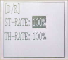
2.14 Steering Dual Rate/Throttle Dual Rate "D/R"
Dual rate
The steering left and right servo travels are adjusted simultaneously. When you want to increase the servo travel, adjust the + side. When you want to decrease the servo travel, adjust the - side.
 Setup Item
Steering D/R
Throttle D/R
RATE
Steering D/R rate (RATE)
0%~100%
Initial value: 100%
Throttle D/R rate (Throttle D/R RATE)
0%~100%
Initial value: 100%
(1) Enter the function menu and use “Dec(-)” or “Inc(+)” button to access D/R function.
(2) Press“Enter” button to get into D/R function interface.
(3) Use “Dec(-)” or “Inc(+)” button to select Steering D/R RATE, press “Enter”key, and the initial value of Steering D/R RATE will blink. Use“Dec(-)”or “Inc(+)” button to make adjustments.
(Note: In the interface of adjusting the value, return to the initial value"100%" by pressing“Dec(-)” and “Inc(+)” buttons simultaneously for about 1 second.)
(4) Press “Enter” key, the adjusted value stops blinking, now the steering D/R RATE has been set.
(5) Throttle D/R RATE can be set similarly.
(6) When ending setting,return to the initial screen by pressing “Exit” button twice.
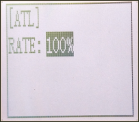 2.15 ATL Function "ATL"
Brake side adjustment
This function decreases the set value when the braking effect is strong and increases the set value when the braking effect is weak.
Setup Item
RATE: Brake amount
Brake amount (RATE)
0%~100%
Initial value: 100%
(1) Enter the function menu and use “Dec(-)” or “Inc(+)”button to access ATL function.
(2) Press “Enter” button to get into ATL function interface.
(3) Press “Enter” key, and the initial value of RATE will blink. Use “Dec(-)”or“Inc(+)” button to adjust the value.
(Note: In the interface of adjusting the value, return to the initial value "100%" by pressing “Dec(-)” and “Inc(+)” buttons simultaneously for about 1 second.)
Press “Enter” button, the adjusted value stops blinking, now the value has been set.
(4) When ending setting, return to the initial screen by pressing“Exit” button twice.
2.16 Programmable Mixes "PMIX"
Programmable mixes between arbitrary channels
These functions allow you to apply mixing between the steering, throttle, CH3, CH4, CH5 and CH6.
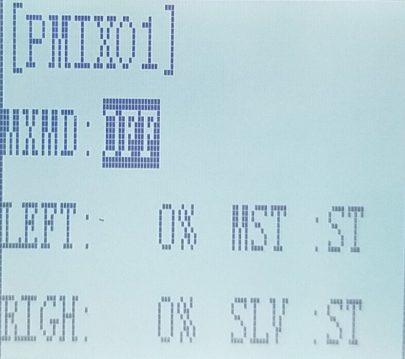
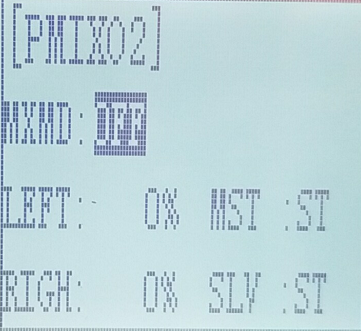 PMIX 01 Setup items
LEFT: Mixing rate (Left side)
RGHT: Mixing rate (Right side)
MST: Master channel
SLV: Slave channel
Programmable Mixes "PMIX"
MXMD:Mix mode
Enter the function menu and use“Dec(-)”or “Inc(+)” button to access PMIX function, then press “Enter” button to get into PMIX function interface.
(1) Master channel
Channel selection (MST)
ST, TH, CH3, CH4, CH5, CH6
Initial value: ST
Select setup item"MST" by pressing “Dec(-)” or“Inc(+)”button, press“ Enter ” button, the initial master channel will blink. Use“ Dec(-)”or“ Inc(+) ” button to select the master channel you wish to adjust, press“Enter” button,the blinking master channel you selected will stop blinking.
(2) Slave channel
Channel selection (SLV)
ST, TH, CH3, CH4, CH5, CH6
Initial value: ST
Select setup item "SLV" by pressing “Dec(-)” or “Inc(+)” button, press “Enter” button, the initial slave channel will blink. Use “Dec(-)” or “Inc(+)”button to select the slave channel you wish to adjust, press “Enter” button, the blinking slave channel you selected will stop blinking.
(3) Left, forward or up side mixing amount adjustment
Mixing amount
-100~0~+100
Select the setting item "LEFT", "FWRD", or "UP"(These setup items are different depend on the master channel. ST: "LEFT"; TH: "FWRD"; CH3:"UP") by pressing “Dec(-)” or “Inc(+)” button. Press “Enter” key, the initial value of "LEFT", "FWRD", or "UP" will blink, Use “Dec(-)” or “Inc(+)” button to adjust the left, forward, or up side mixing amount.
(Note: In the interface of adjusting the value, return to the initial value "0" by pressing“Dec(-)” and “Inc(+)” buttons simultaneously for about 1 second.)
Press “Enter” key, the adjusted value stops blinking, the selected mixing amount has been adjusted.
(4) Right, brake or down side mixing amount adjustment
Mixing amount
-100~0~+100
Select the setting item "RGHT", "BRAK", or "DOWN"(These setup items are different depend on the master channel.ST:"RGHT"; TH:"BRAK";CH3:"DOWN") by pressing “Dec(-)” or “Inc(+)” button. Press“Enter”key,the initial value of "RGHT", "BRAK", or "DOWN" will blink, Use“Dec(-)”or“Inc(+)”button to adjust the right, brake, or down side mixing amount.
(Note: In the interface of adjusting the value, return to the initial value "0" by pressing “Dec(-)” and “Inc(+)” buttons simultaneously for about 1 second.)
Press “Enter” key, the adjusted value stops blinking, the selected mixing amount has been adjusted.
(5) Mixing mode setup
Mixing mode (MXMD)
OFF, MIX
Initial value: OFF
Select setup item"MXMD"by pressing“Dec(-)”or “Inc(+)” button, press “Enter “ button, the initial mixing mode“OFF”will blink. Press“Dec(-)”or “Inc(+)”button to switch “OFF” to “MIX”, press “Enter” button, the blinking “MIX” will stop blinking.
"OFF": Mixing proportional to master channel operation.
"MIX": Mixing by master channel another function considered.
(6) When ending setting, return to the initial screen by pressing “Exit” button twice.
PMIX02 setting is the same as the PMIX01.
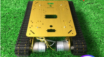
Take a dual-engine model (eg. Tracked vehicle) as an setting example.
Working theory of tracked vehicles
RC Cars: One execute unite of radio controls a movement of a car (eg. Steering wheel to Ch1-Direction to turn left/right). Every R/C channel operation and every execute unite of car is ONE TO ONE.
Dual-engine Models: Being dual-engine category, tracked vehicle has two motors and each track is driven by each motor.
Mix Control: The throttle (a function) on R/C monitors two motors(two execute unites) move forward/backward simultaneously. That is, ONE TO TWO mix control. On the other hand, the turning of steering wheel makes one motor forward while the other backward at the same time to achieve direction turning. Same as ONE TO TWO mix control.
Dual Mix Control: As controlling dual-engine vehicles drive forward/backward and turn left/right, two mix controls at the same time are needed. RADIOLINK RC6GS has two programmable mix controls.
Reverse Setup before Mix Control Setup
Before setting the mix controls, please check if the reverses working correctly by testing its wheel and throttle. Take steering wheel-- left track (Ch1 on receiver) and throttle--right track(Ch2 one receiver) as example.
Throttle Reverse:NOR-REV
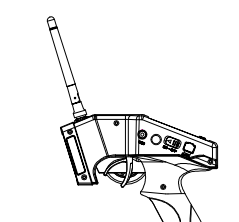
Hold RC6GS as the below pic. Normally, pull the throttle, the right track should be moving forward while push the throttle and the right track should be backward.


If pulling the throttle and the left track moves backward; Or pushing the throttle and the left track moves forward, meaning the initial throttle is reversed and needs to be set. Please refer to the “button operation”and get into below interface to complete the setup.

* If the throttle reverse is correct, skip this throttle reverse setup.
Steering Reverse:NOR/REV
Hold RC6GS as the below pic. Normally, if turn the wheel right/clockwise, the left track should be moving forward while turn the wheel left/anticlockwise and the left track should be backward.
If turning the wheel right and the right track moves backward; Or turning the wheel left and the right track moves forward, meaning the initial steering is reversed and needs to be set. Please refer to the “button operation”and get into below interface to complete the setup.
* If the steering reverse is correct, skip this steering reverse setup.
After setting the throttle/ steering reverse, then mix control can be set.
Mix Control Setup
Throttle mix steering:Tracked vehicles moving forward/backward
As tracked vehicles moving forward/backward is controlled by throttle, throttle leads steering in the mix control. That is, Master-Throttle, Slave-Steering. Please refer to the “button operation”and get into below interface to complete the setup.
* Percentage value varies the speed;
”+”means Master and Slave move to same direction at the same time
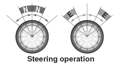
Steering mix Throttle:Tracked vehicles turning left/right
As tracked vehicles turning left/right is controlled by steering, steering leads throttle in the mix control. That is, Master-Steering, Slave-Throttle. Please refer to the “button operation”and get into below interface to complete the setup.
* Percentage value varies the turning angle;
”-”means Master and Slave move to different directions at the same time
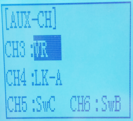
2.17 Channel 3 Position "AUX"
The channel 3 and channel 4 servo position can be set from the transmitter. When CH3 is assigned to the 3rd channel key, this setting is linked to the key. When CH3 and CH4 is not assigned to the 3rd channel key, it can be set with this screen.
You can also set the CH3, CH4, CH5 and CH6 as VR at the same time, or SW.
Channel 3 position (POSI)
SW(LOCK) or VR(RATE)
Channel 4 position (POSI)
SW(LOCK) or VR(RATE)
Channel 5 position (POSI)
SW(LOCK) or VR(RATE)
Channel 6 position (POSI)
SW(LOCK) or VR(RATE)
(1) Enter the function menu and use “Dec(-)” or “Inc(+)” button to access AUX function.
(2) Press “Enter” button to get into CH3, CH4, CH5 or CH6 function interface.
(3) Use “Dec(-)” or “Inc(+)” button to select Channel setup item.
Use “Dec(-)” or “Inc(+)” button to select POSI, press“Enter”key and the value will blink, use “Dec(-)” or “Inc(+)” button to select “VR” or “SW”.
Press “Enter” button, the adjusted value stops blinking, now the value has been set.
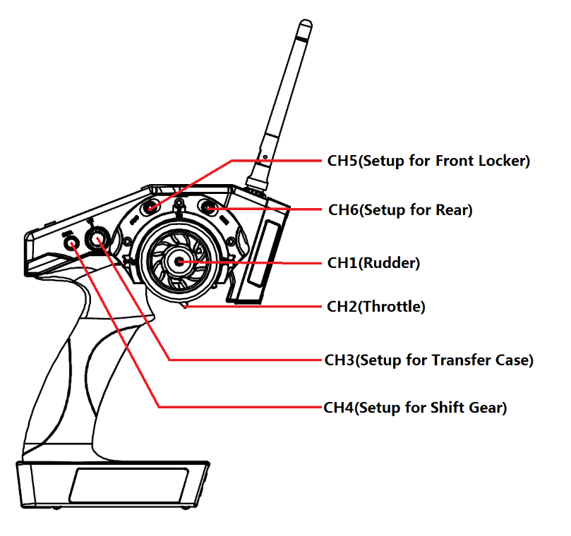
If you use RC6GS to control RC crawler, you can setup each channels as below.
CH1 is rudder,
CH2 is throttle,
CH3 can setup to control the transfer case,
CH4 can setup to control the shift gear,
CH5 can setup to control the front locker and
CH6 can setup to control the rear.
2.18 Model Name "NAME"
RC6GS stores model memories for ten models. Each model memory can be named separately according to user’s requirement.
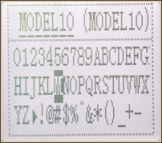 Factory default name: MODEL1
(1) Enter the function menu and use “Dec(-)” or “Inc(+)” button to access NAME function.
(2) Press “Enter” button to get into NAME function interface, the first character of current name will blink, and the blinking character can be reset. The common use characters appear at the bottom of the screen, use “Dec(-)” or “Inc(+)” button to choose the character you desired.Press“Enter” button again, the next character of current name will blink. Reset other characters of current name in same manner.
(3) After accomplishment of naming, all characters of current name will stop blinking, the new name will be stored automatically.
(4) When ending setting,return to the initial screen by pressing“Exit”button twice.(the new setting model name will appear on the initial screen)
2.19 Low Voltage Alarm
 The transmitter’s low voltage alarm adjustable, it depends on what kind of battery, the 4.6V is may cause the battery over discharge and damage the battery. So you can set transmitter’s warning voltage when you use different battery.
There are four options you can choose:
Li2S-7.4V
Li3-11.1V
Ni4S-4.6V
ALARM: adjustable 4.0V to 16.0V
The car will be out of control if the battery runs out, please immediately stop running when the alarm starting to ring.
2.20 Gyro Sensitivity
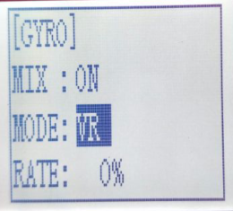 This function is available to set gyro sensitivity and VR mixing ON or OFF.
When MIX set OFF, gyro is disabled while when MIX set ON, you can adjust gyro sensitivity STD or VR. STD is adjusted on screen and VR is default CH3.
In normal mode (STD), range of sensitivity is 0%-100%.
(1) Enter the menu, use Dec(-) and Inc(+) to select options for gyro sensitivity.
(2) Press the key button “Enter” to enter sub-menu gyro sensitivity.
(3) Press “Enter” again, the initial value will start flashing, then use Dec (-) and Inc (+) to change the value.
(4) Press the button key “Enter”, the value stops flashing, the setting is finished now.
(5) "Mode"and "Rate" can also be set by the same step.
(6) Press button key “Exit” to be back to initial screen.
2.21 Fail Safe
This function is set by servo, throttle, CH3, CH4, CH5 and CH6.
Option:
ST: Steering(CH1)
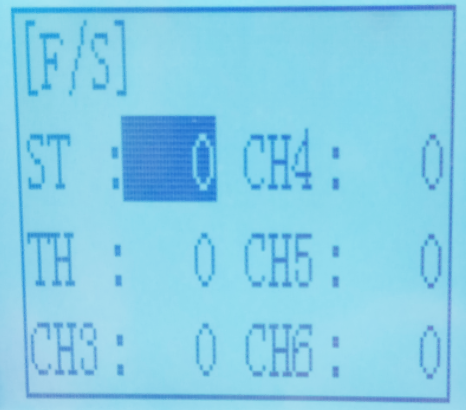 TH: Throttle(CH2)
CH3: Channel3(VR)
CH4: Channel4(SWA)
CH5: Channel5(SWB)
CH6: Channel6(SWC)
RANGE:
Servo: -100~+100
Throttle: -100~+100
CH3: -100~+100
CH4: -100~+100
CH5: -100~+100
CH6: -100~+100
Initial value: 0
(1) Enter the menu, use “Dec (-)” and “Inc (+)” to select options to set.
(2) Press the button key “Enter” to enter menu.
(3) Use “Dec (-)” and “Inc (+)” to select SERVO, then press “Enter”. Now the initial value
of SERVO will start flashing, use handle to change the value.
(4) Press the button key “Enter”, the value stops flashing, now the value of SERVO is set.
(5) THROTTLE is to set by the trigger.
CH3 is to set by VR controller.
CH4 is to set by the button switch.
CH5 is to set by the toggle switch.
CH6 is to set by the toggle switch.
(6) Press “Exit” two times to back to initial screen.
2.22 ID SEED
ID SEED function means designating a subsidiary ID among multiple binding receivers to realize the control. There are totally 10 independent subsidiary IDs can be stored.
For example, RC6GS has completed the binding with 10 different boats and the setup of respective parameters. Turn on the ID SEED function, select ID.1 boat and drive it to the central of water but it stops working unexpectedly. Then we can change to the ID.2 boat (or any other subsidiary ID boat preferred) and control it independently to rescue ID. 1 boat instead of controlling both boats at the same time, which makes the rescue more difficult. Unlike traditional binding mode, independent ID can easily realize rescuing stalled boat in the water caused by various reasons.
Press EXIT and ENTER simultaneously to enter MENU=>press Inc(+)/DEC(-) to highlight “22. ID SEED=>Press ENTER => Change the MODE from OFF to ON=> set the subsidiary ID number=> complete biding and parameters setting.
Once finished , the corresponding ID number will be displayed on the RC6GS main interface .
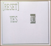 2.23 RESET
RESET- Data reset function:
All the data for any model memory can be reset to original factory defaults. Often this function is done to get a “fresh start” and clear the memory before inputting new model settings.
(1) Enter the function menu and use “Dec(-)” or “Inc(+)” button to access RESET function.
(2) Press “Enter” button to get into RESET function interface, the symbol “YES” will blink.
Be sure to reset
Press “Enter” key, the symbol “YES” will stop blinking, and return to the initial screen. Now the model data is reset to the initial setting that is the default value set at the factory.
Not to reset
Press “Dec(-)” or “Inc(+)” button, the symbol “YES” will stop blinking and the symbol “NO” will blink, press “Enter” key, the symbol “NO” will stop blinking, return to the initial screen by pressing “Exit” button twice.
Or you can press “Exit” button twice to quit resetting directly.
CAUTION: Resetting the current model memory will permanently erase ALL programming information for that model. The data cannot be recovered. Do not reset the model unless you are certain you want to clear-out that memory and start from scratch.
Thank you again for choosing our product