
Chapter 1 RC8P Remote Control System
1.1 Safety Precautions
1.Do not operate outdoors on rainy days, run through puddles of water, or use when visibility is limited. Should any type of moisture (water or snow) enter any component of the system, erratic operation and loss of control may occur.
2.Do not operate in the places that near people or roads.
3.This product is not a toy and is NOT suitable for children under the age of 14. Adults should keep the product out of the reach of children and exercise caution when operating this product in the presence of children.
4.Please strictly abide by local laws and regulations when using the product!
5.Always check the throttle trigger on the transmitter to be sure it is at the neutral position before turning on the power switches of transmitter and receiver. Always be sure the engine is not running or the motor is stopped before turning off the power switches.
6.Please turn off the power supply of the receiver and controlled equipment first, and then turn off the transmitter. If the operation is reversed, it may cause loss of control and cause an accident!
7.Please be sure to remove the battery if the transmitter will be remained unused for an extended period. Batteries left in the device for too long or allowed to over-discharge are prone to leaking and corrosion, which can damage the internal circuit board and metal contacts of the transmitter, creating safety hazards such as short circuits and component failure.
8.Note: The input voltage for the Type-C port of RC8P is 5V. When the Type-C port is used to to charge or power the RC8P, the input voltage cannot exceed 5V. Otherwise the circuit board will be damaged.
1.2 RC8P Introduction
1.2.1 Specifications
RC8PTransmitter | |
Dimension | 124.32*147.39mm(4.89"*5.8") |
Weight | 193g(6.81oz) |
Battery Case Dimension | 18*65mm |
Antenna Length | Built-in antenna |
Channels | 8 fully proportional channels. The switches of all 8 channels can be customized |
Output Frequency | 2.4GHz ISM band(2400MHz~2483.5MHz) |
Spread Spectrum | FHSS 67 channels pseudo-random frequency hopping |
Operating Systems | FreeRTOS+LVGL GUI |
Voice Broadcast | Unique personalized and humanized voice broadcast customization |
Response Latency | 3ms, 4ms, 14ms can be selected |
Channel Resolution | 4096 with regular jitter of 0.25us |
Modulation Mode | GFSK |
Channel Band Width | 400KHz |
Channel Pacing | 1200KHz |
Transmitter Power | <100mW(20dBm) |
Adjacent Channel Rejection | >36dBm |
Transmission Rate | 38kbps |
Reception Sensitivity | -104dBm |
PWM Output Range | 875-2125 |
Cycle | 15ms/per frame |
Operating Voltage | 3.4V~4.2V (one 18650 battery) |
Operating Current | 230mA(±15mA)@4.2V DC |
Type-C Port Specifications | Input Voltage: 5V(Can be charged by a computer or a mobile power bank via Type-C cable) Input Current: 500mA |
Control Distance | 600 meters(1968.5ft) (Maximum range tested in unobstructed areas free of interference) |
Applicable Model Types | Car (Including Crawlers, Drag Racing Cars, Tanks, Caterpillars), Boat, Robot |
Signal Support | PWM&SBUS&PPM |
Trainer Function Signal | PPM |
Low Voltage Alarm | Low transmitter voltage, low receiver voltage, low model battery voltage, or low RSSI alarm can be customized |
Storage Model Quantity | 30 |
Sub ID Models Quantity | 16 |
Simulator Function | Except traditional simulators like Phoenix, RC8P features built-in simulator support. With no external dongle needed, connect it to your computer via a Type-C cable to seamlessly use open-source simulators such as TRYP FPV, AeroFly, Uncrashed, Liftoff, FPV LOGIC, and Velocidrone - compatible with macOS and Windows systems. |
Trainer Function | Supports both the wireless and the wired trainer mode |
Screen | 2.4 inches, 16 colorful screens, 320*240 pixels |
Compatible Receivers | R8FG, R16F, R16SM, R12F, R12FL, R8FGH, R8EF, R8FM, R8SM, R8XM, R7FG, R6FG, R6F, R4FGM |
Operating Temperature | -30° to 85° C |
R8FG Receiver | |
Dimensions: | L*W*H =35*24*13.5mm (1.38”*0.94”*0.53”) |
Antenna Length: | 205mm (8.07”) |
Weight: | 10.5g(0.37oz) |
Channel: | 8 channels |
Signals: | SBUS+PWM |
Operating Voltage: | 3-12V |
Operating Current: | 35mA(5V) |
Frequencies Band: | 2.4GHz ISM band (2400MHz~2483.5MHz) |
Spread Spectrum Mode: | FHSS, 67 channels pseudo-random frequency hopping |
Section Precision: | 4096, 0.25us per section |
Telemetry: | Real-time built-in telemetry of the model battery voltage, RSSI, and receiver voltage |
Gyro: | Receiver with gyro-integrated, customizable gyro sensitivity |
Water Splash Proof: | The waterproof grade is IPX4 |
Applicable Model Types: | Car (Including Crawlers, Tanks, Caterpillars), Boat, Robot |
Response Latency | 3ms, 4ms, and 14ms can be selected (R8FG is V2.1 or R8FG with a factory date of 2023/4/26 and later.) |
Control Distance: | 600 meters |
Compatible transmitter: | RC8X, RC8P, RC6GS V3, RC4GS V3, RC6GS V2, RC4GS V2, RC6GS, RC4GS;T16D, T12D, T12S, T8FB, T8S |
1.2.2 Packing List
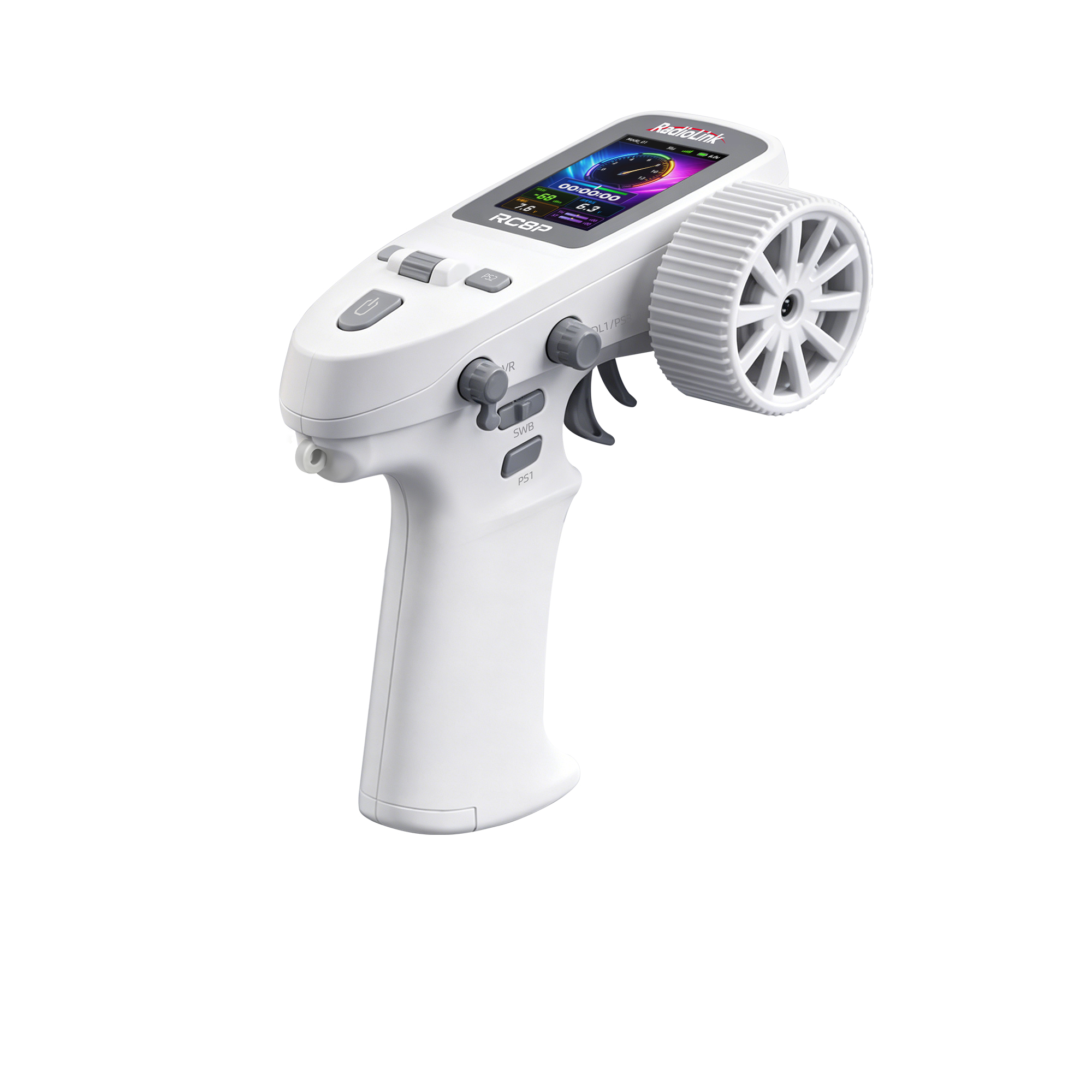
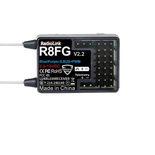
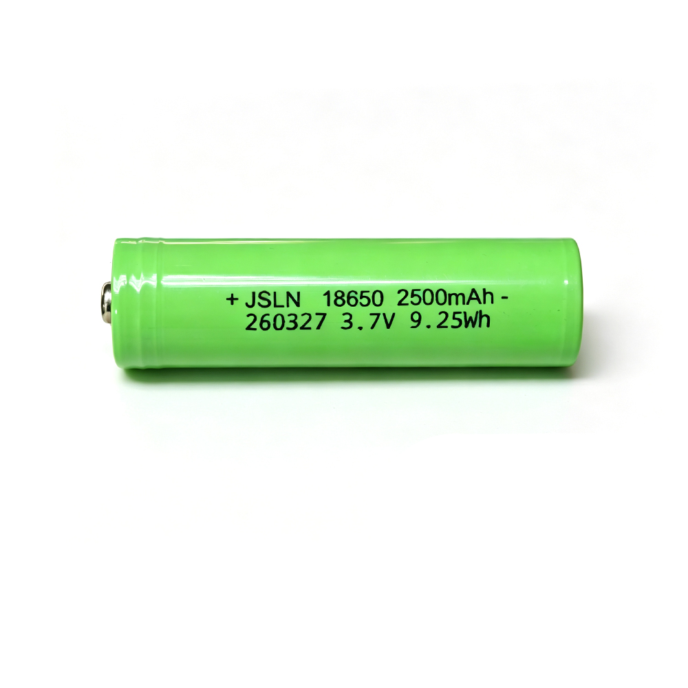
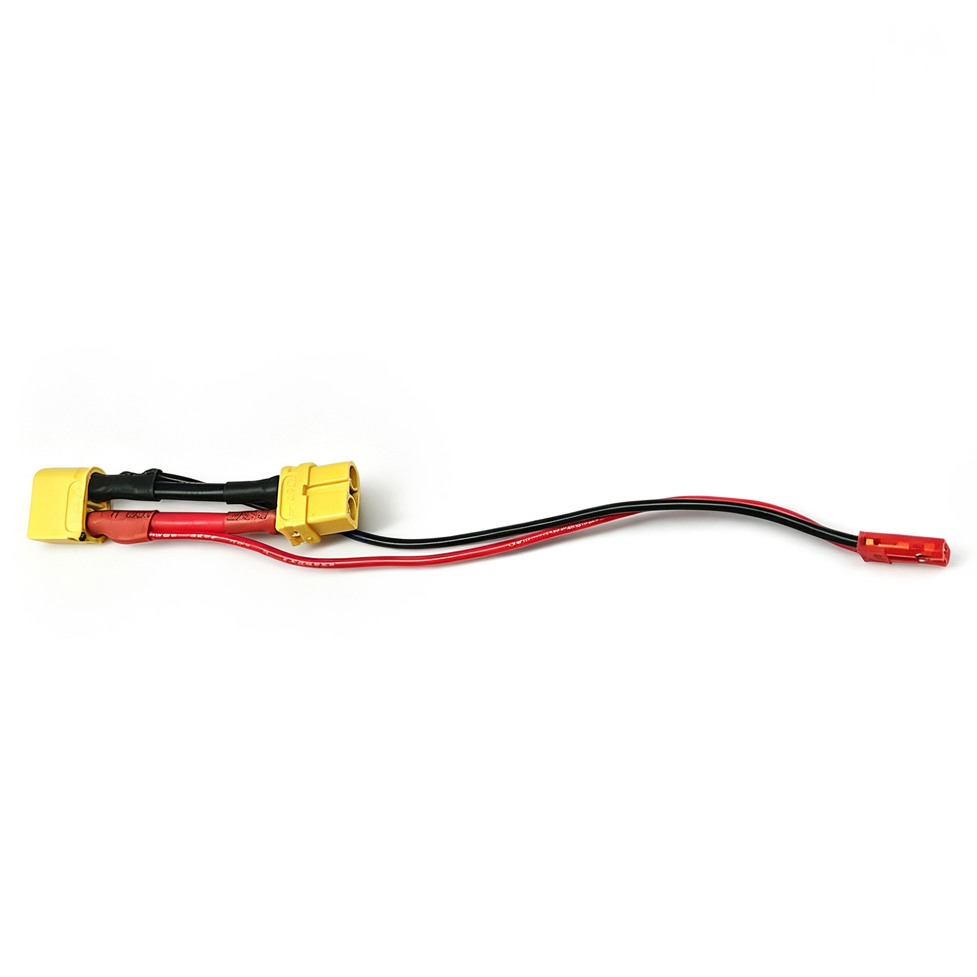
RC8P Transmitter*1 R8FG Receiver*1 18650 Battery *1 Model Voltage Telemetry Cable*1
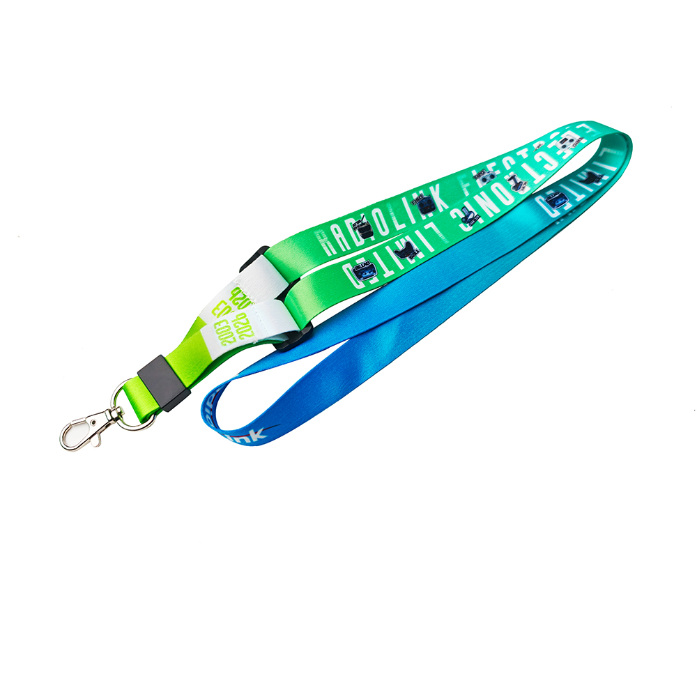
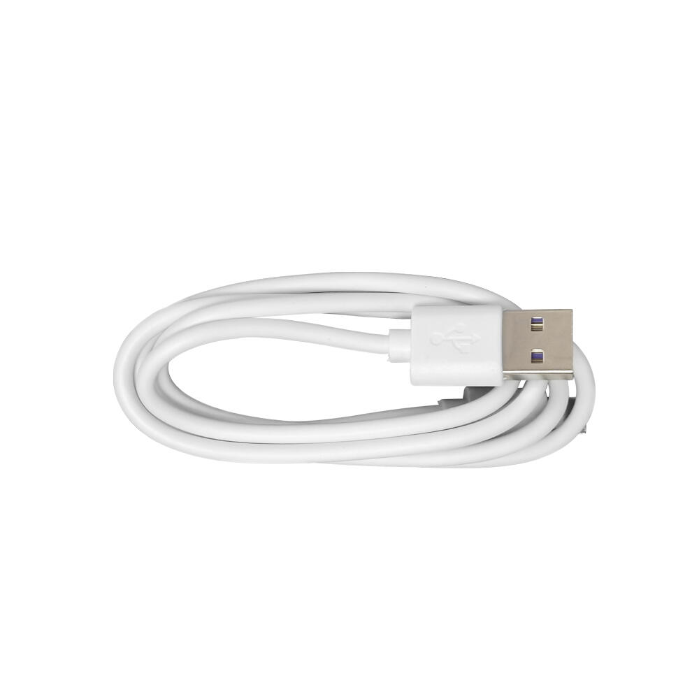
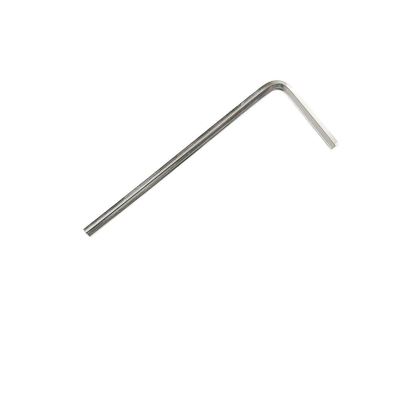
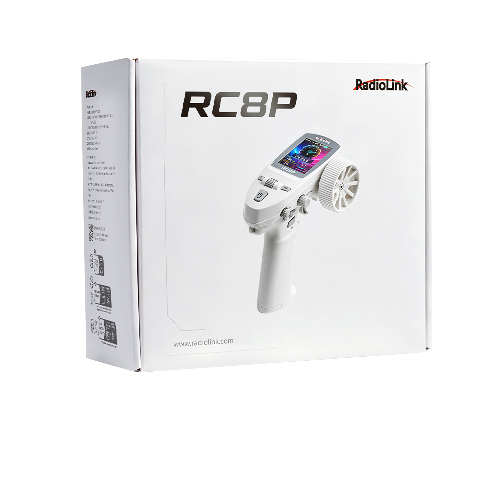
Lanyard*1 Type-C Cable*1 2.0mm Hex Wrench*1 Manual*1 Packing Box*1
Note: RC8P is available in multiple casing colors, but the functionality remains the same. White RC8P is used as an example in this manual.
1.2.3 RC8P Overview
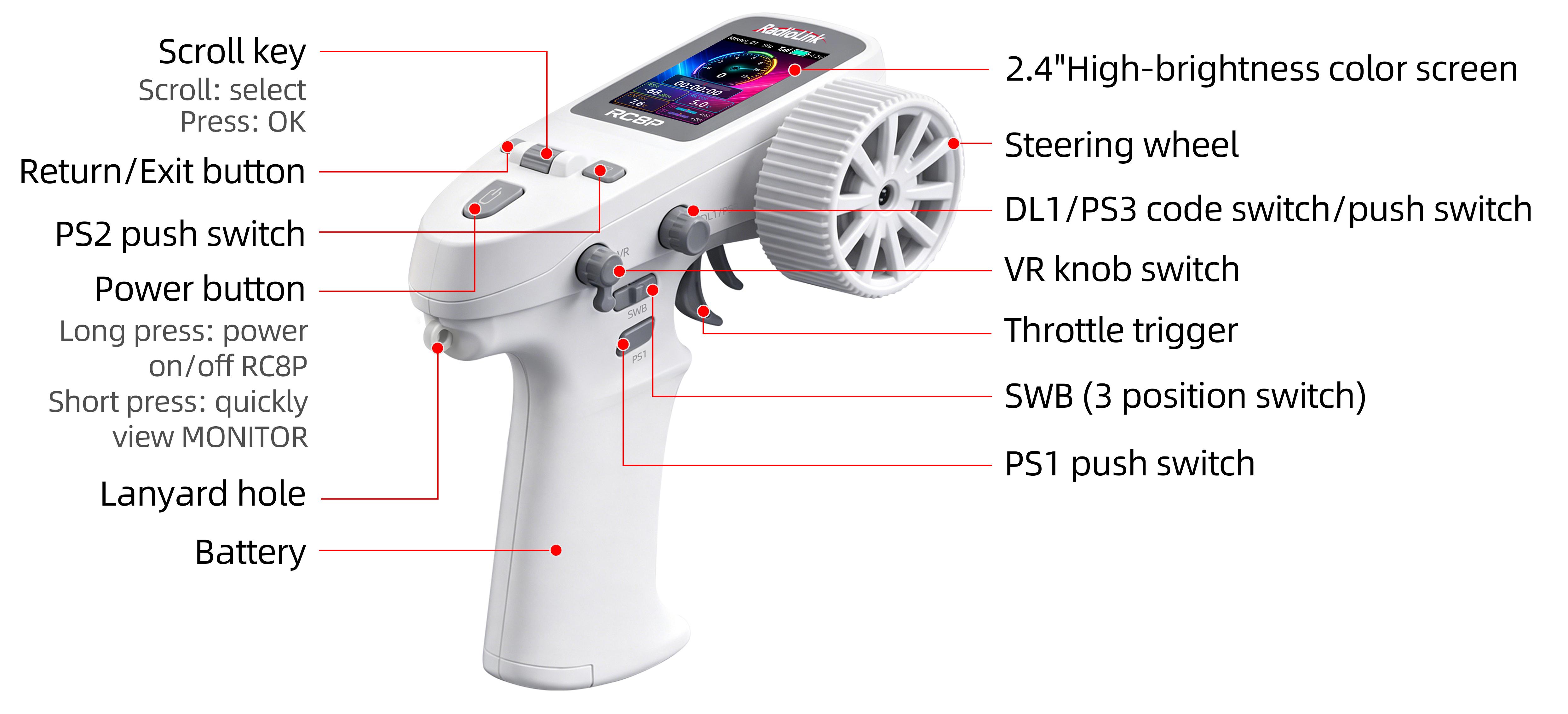
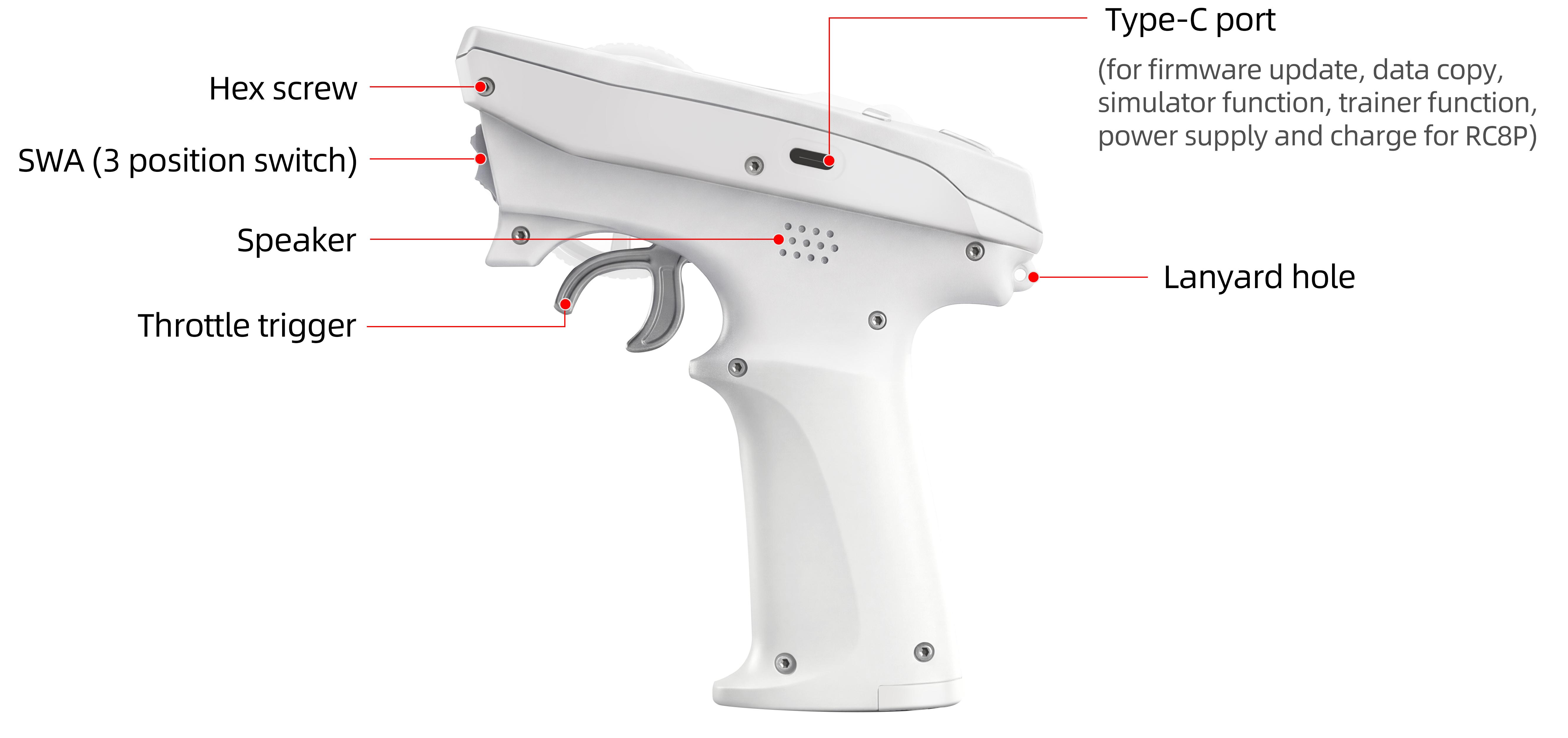
1.2.4 Power Supply for RC8P
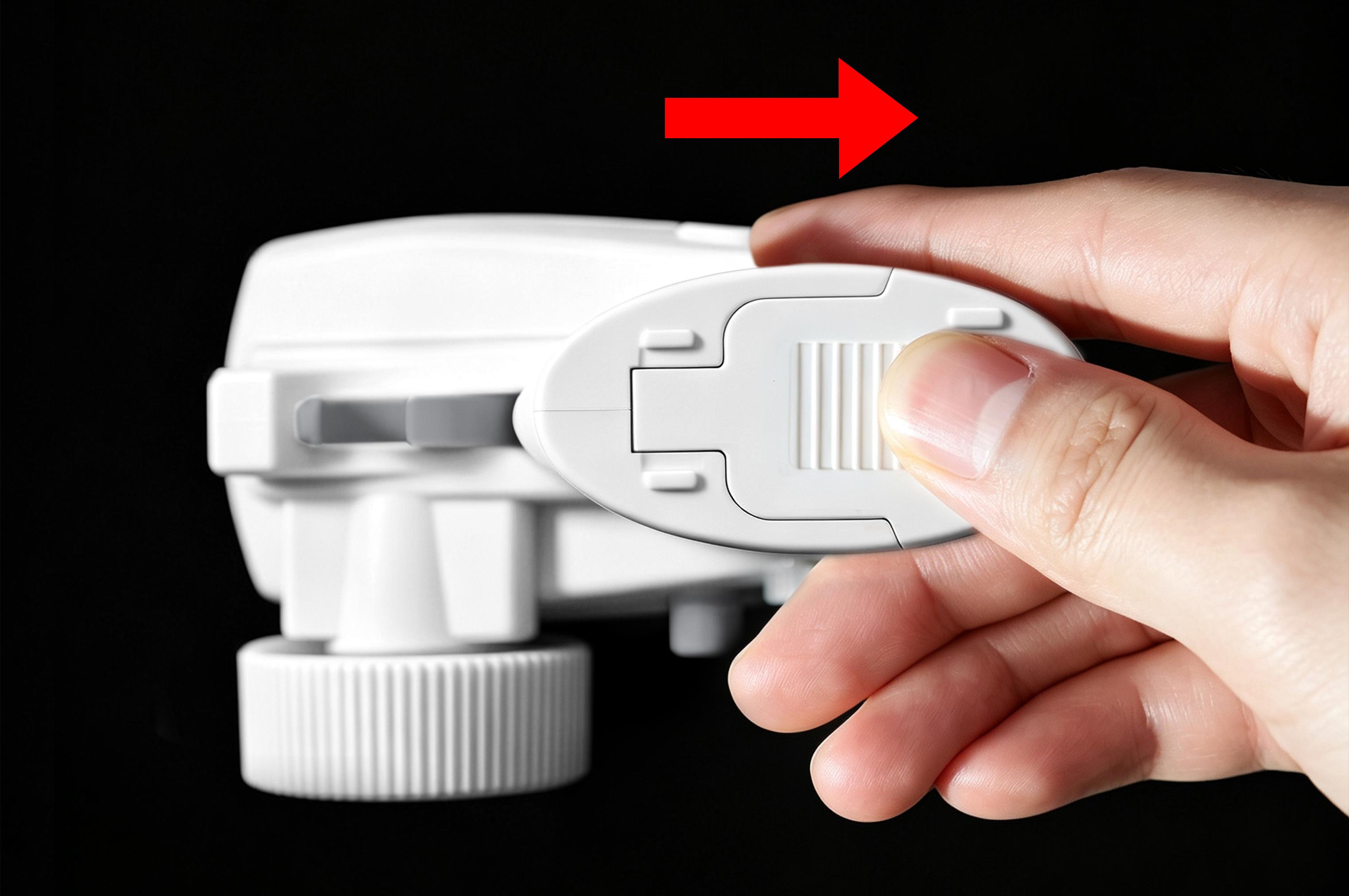
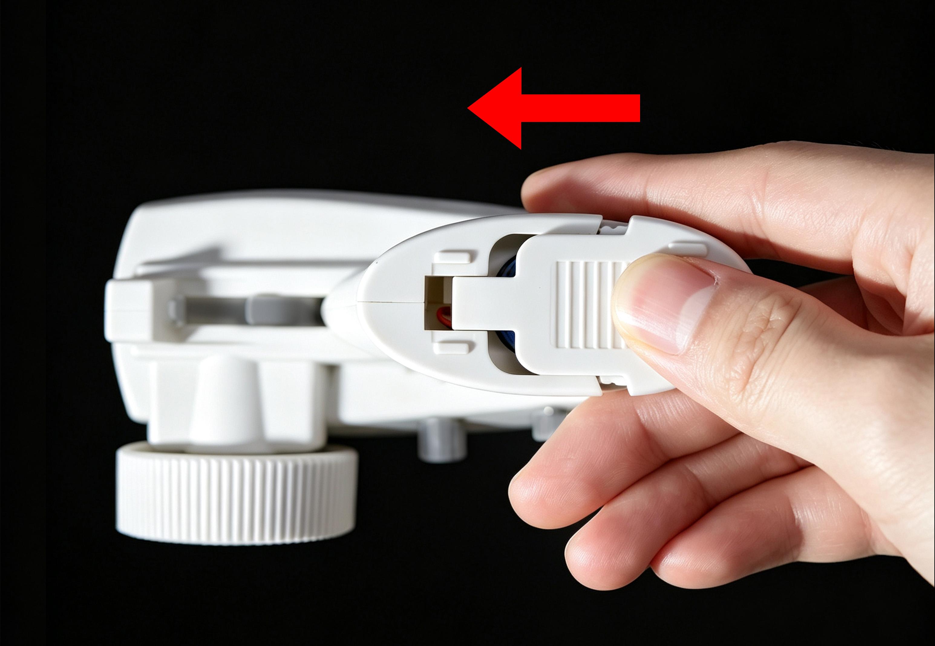
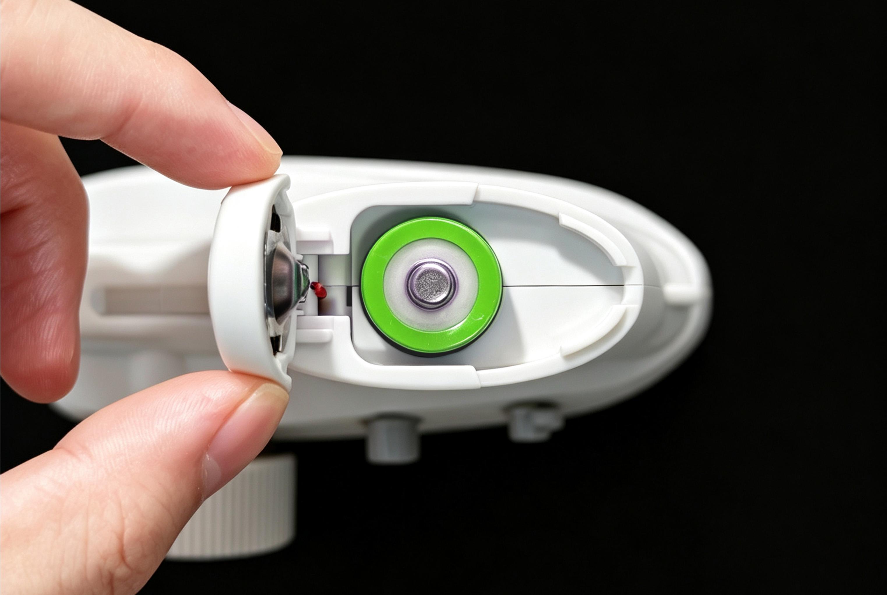
RC8P operates within a voltage range of 3.4V to 4.2V and comes with a 18650 battery. Install the battery and you can power on the transmitter. Users can charge the battery by connecting RC8P to a computer or power bank via a Type-C cable (Note: The input voltage for the Type-C port of RC8P is 5V, so please ensure that the voltage used for charging or temporary power supply does not exceed 5V). After connecting a Type-C cable, a red light on the power button indicates that the 18650 battery is charging, while a blue light indicates the battery is fully charged. If the Type-C cable is connected without a battery inserted, the power button will flash red and blue alternately (long blue flash and short red flash). To install or remove the 18650 battery, please follow the steps below:
Slide the battery cover flat in the direction of the arrow and release it. The cover will automatically pop open:
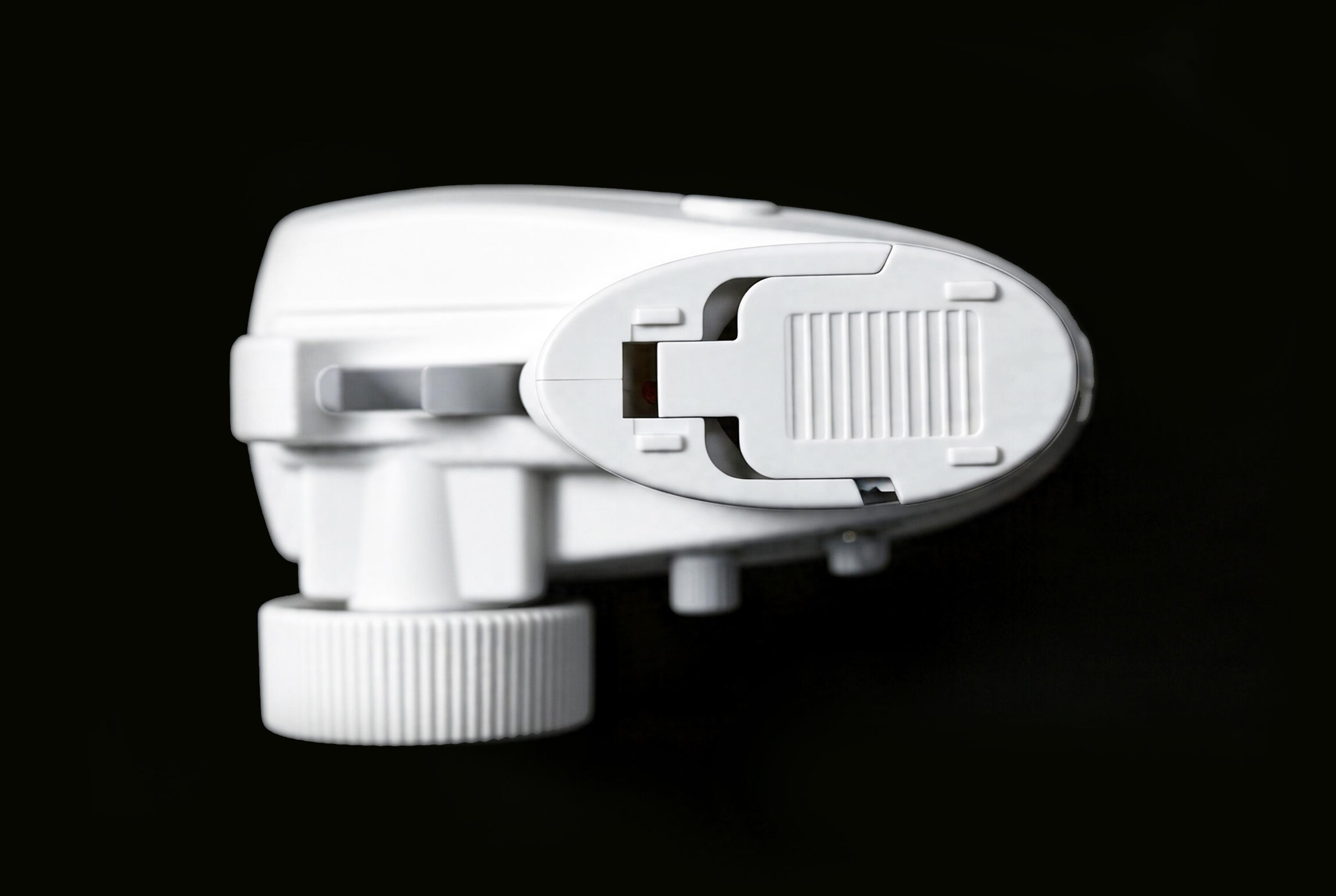
To install the 18650 battery into the battery compartment, please ensure the positive terminal (the protruding end) faces outward; then, and press down on the battery cover and slide it back into place in the direction of the arrow.
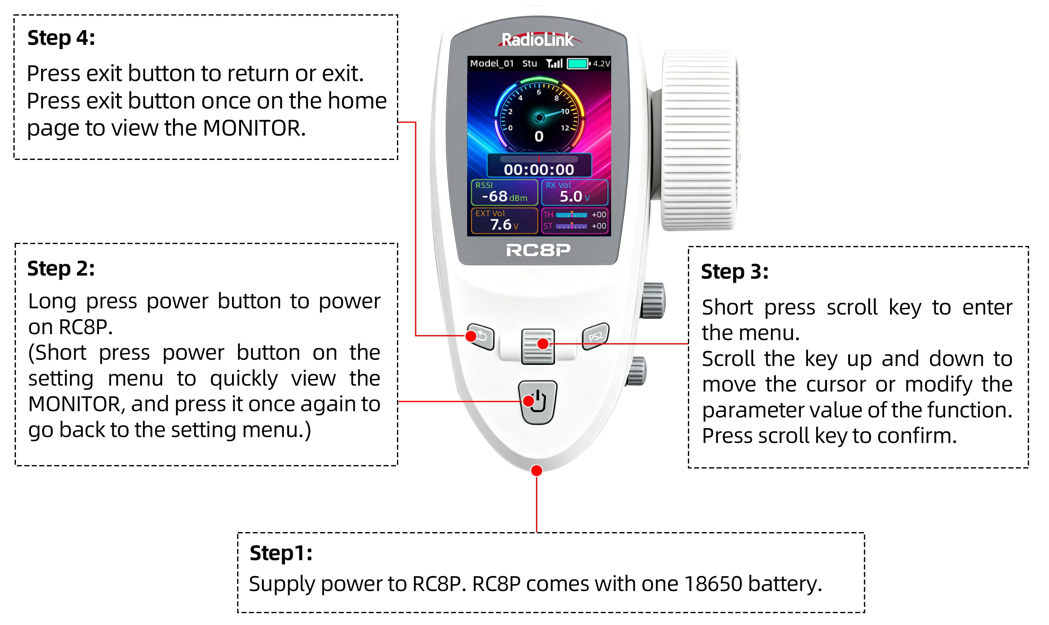
1.2.5 Transmitter Basic Operation
1.2.6 Power on RC8P
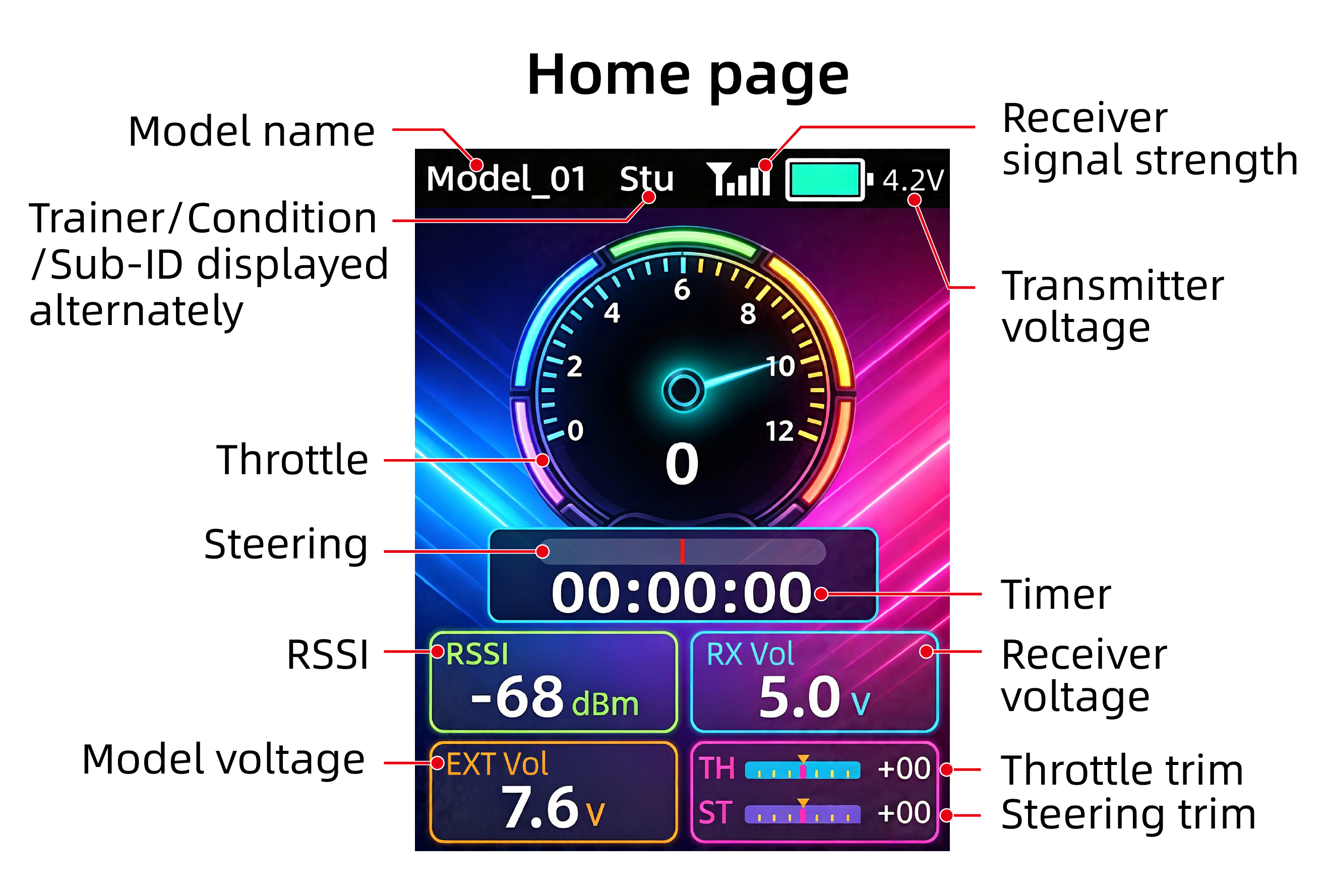
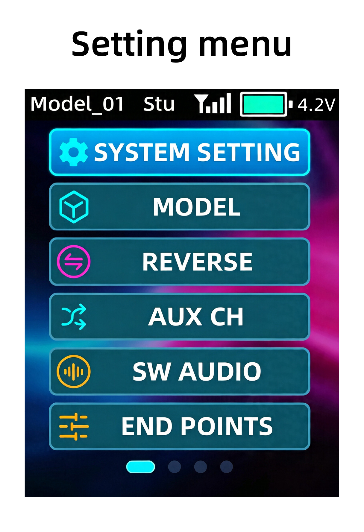
Long press the power button to power on RC8P. The short press the scroll key to enter the setting menu.
1.2.7 Language Select
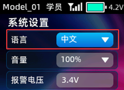 Short press the scroll key to enter the menu. If the language is displayed as Chinese, please scroll the key up and down to move the cursor to 系统设置. Short press the scroll key to enter the system setting interface, and change the language from Chinese (语言:中文) to English, as shown on the right.
1.2.8 Transmitter Low Voltage Alarm
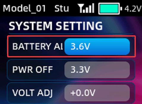 Transmitter low battery voltage alarm is 3.6V by default. If the battery voltage of transmitter is lower than 3.6V, RC8P will make a voice broadcast to warn you the battery voltage is low. The power off voltage is 3.3V by default. When the battery voltage reaches 3.3V, RC8P will be powered off automatically. The battery voltage alarm value can be set based on your needs.
Setting method: Short press the scroll key to enter SYSTEM SETTING--BATTERY ALARM.
1.3 R8FG Introduction
1.3.1 Features of R8FG
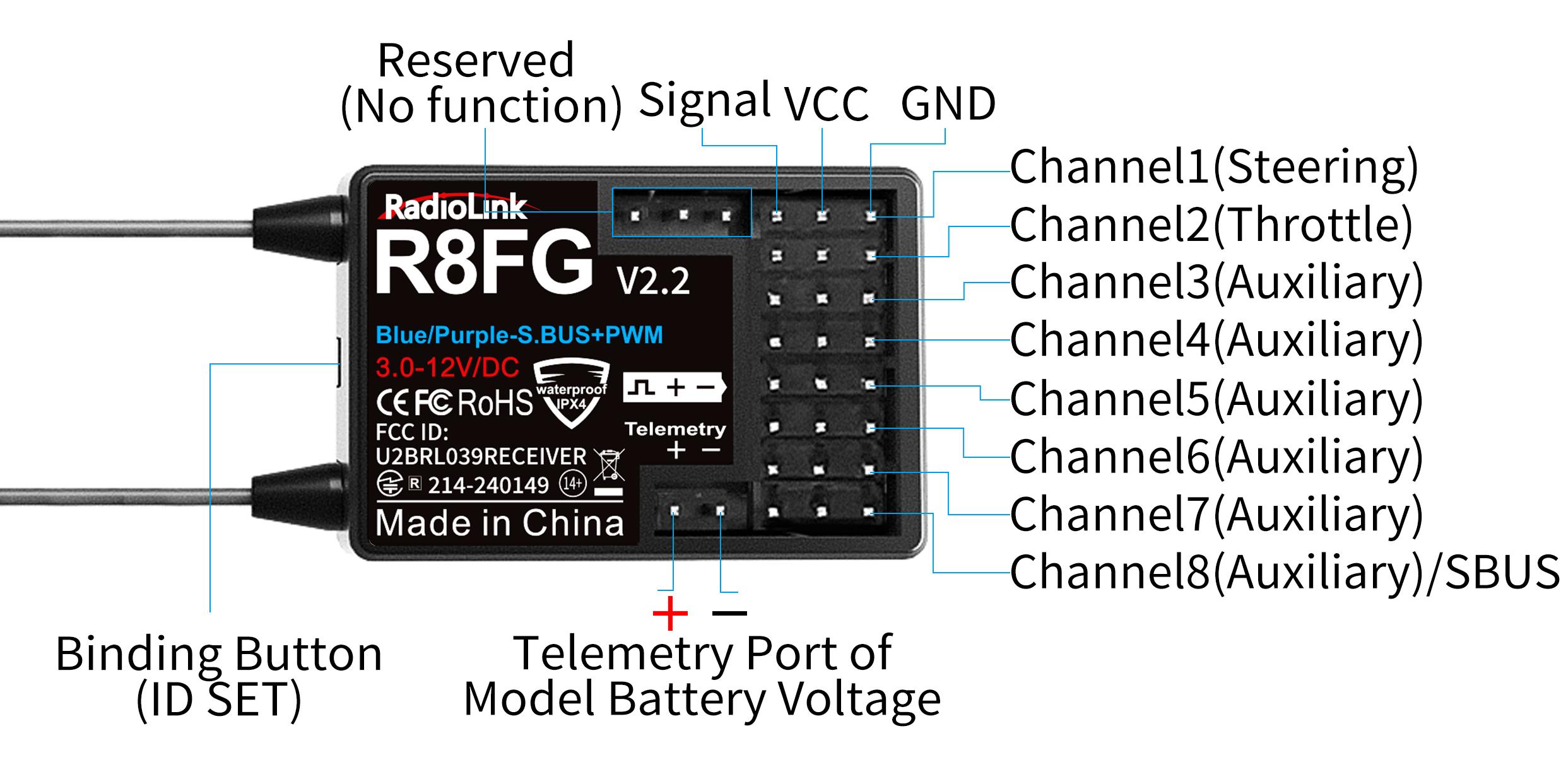
RC8P transmitter comes with a R8FG, 2.4GHz 8-channel receiver, gyro integrated and high voltage servo supported.FHSS spread spectrum algorithm and 67-channel pseudo-random frequency hopping make the R8FG get excellent anti-interference performance, perfect for multiplayer complete synchronously.R8FG also support PWM and SBUS signals output.
Note: The gyro function of R8FG is disabled by default (indicated by a green light). To enable the gyro function, please refer to Chapter 1.3.5 Gyro Function of R8FG.
Note: Please do the following safety check before operating your model:
RSSI test (Received Signal Strength Indicator). For test method, please refer to the manual Chapter 1.3.7 RSSI Testing.
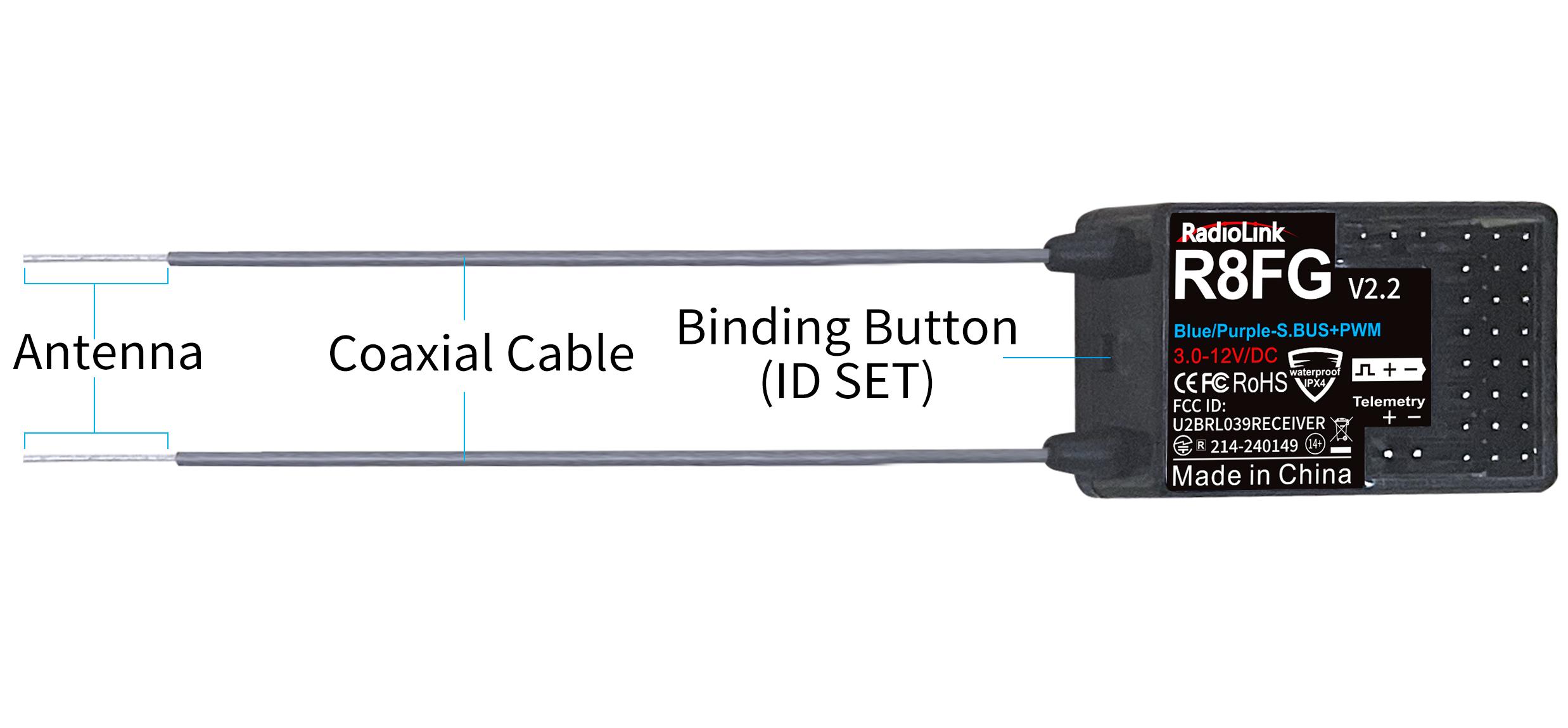
Antenna inspection: The gray line on R8FG is coaxial cable, while the transparent line with a length of about 4-5 centimeters at the top is antenna. If the transparent line is broken or damaged, it will directly affect the control distance, so please replace the receiver antenna in time.
1.3.2 Binding
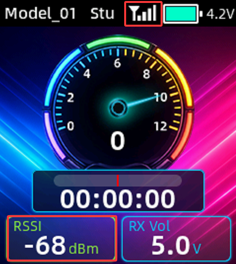
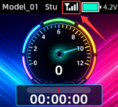 RC8P and R8FG have finished binding by default. Turn on the RC8P and the R8FG, the signal tower will show on the top of the screen as shown on the right, it means the transmitter and receiver has finished binding.
But if you buy a new receiver for your RC8P. Each receiver has an individual ID code and must bind with transmitter before using. When the binding is done, the ID code will be stored in the transmitter and there's no need to rebind.
Binding steps:
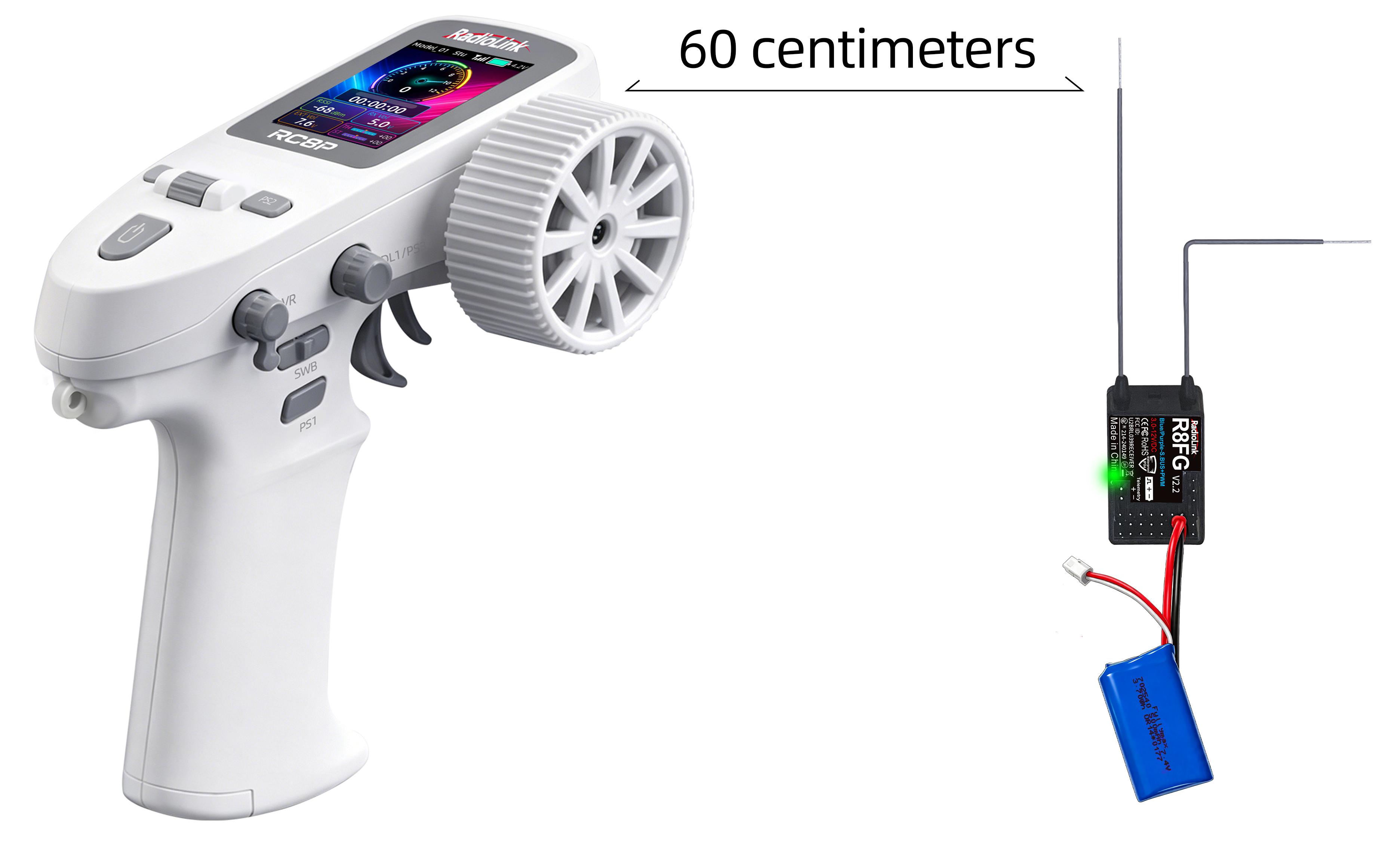
① Put the transmitter and the receiver close to each other (about 60 centimeters). Note: The close distance of the transmitter and receiver may cause signal block, which leads to unsuccessful binding or signal loss.
② Turn on both the transmitter and the receiver, and then the LED of R8FG will start flashing slowly.
③ There is a black binding button (ID SET) on the side of receiver. Press the button for more than 1 second and release, the LED will flash quickly, indicate binding process is ongoing.
④ When the LED stops flashing and is always on, binding is complete and there will be a signal tower shown on top of the LCD screen of the transmitter. If not succeed, the LED will keep flashing slowly to notify, repeat the above steps.
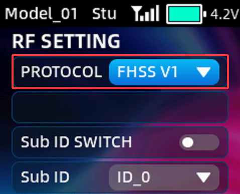 Note: If the receiver you are using is not R8FG, but other receivers such as R7FG, R6FG, etc., please select "FHSS V1" in the RF setting menu (as shown on the right), and then bind them. If the communication protocol of the receiver is selected incorrectly, binding will fail. Please refer to the Chapter 2.7 RF Setting for more details of the receiver and the corresponding protocol.
R8FG binding tutorial: https://www.youtube.com/watch?v=uDIiyr9tmYA
1.3.3 Receiver Connection
(1)Connect Cable
Picture 1 Picture 2
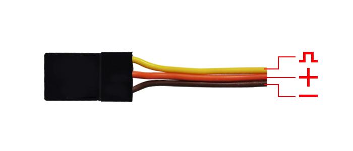
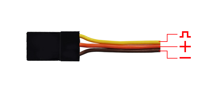
The connection wire for the receiver is shown in the picture above. The common ones are white/red/black wire (Picture 1) or yellow/red/brown wire (Picture 2). The two types of servo cables both are light-colored wire as the signal wire, and dark-colored wire as the ground wire, and the middle is 5V power supply, and the three wires correspond to "  " on the sticker of the receiver.
Note: RadioLink receivers are all designed with anti-polarity connect protection. When the receiver is powered by a separate battery, the receiver will not be damaged if the battery polarity is reversed, but if the servo is connected at this time, it will damage the servo.
(2)Connect R8FG for Telemetry Function
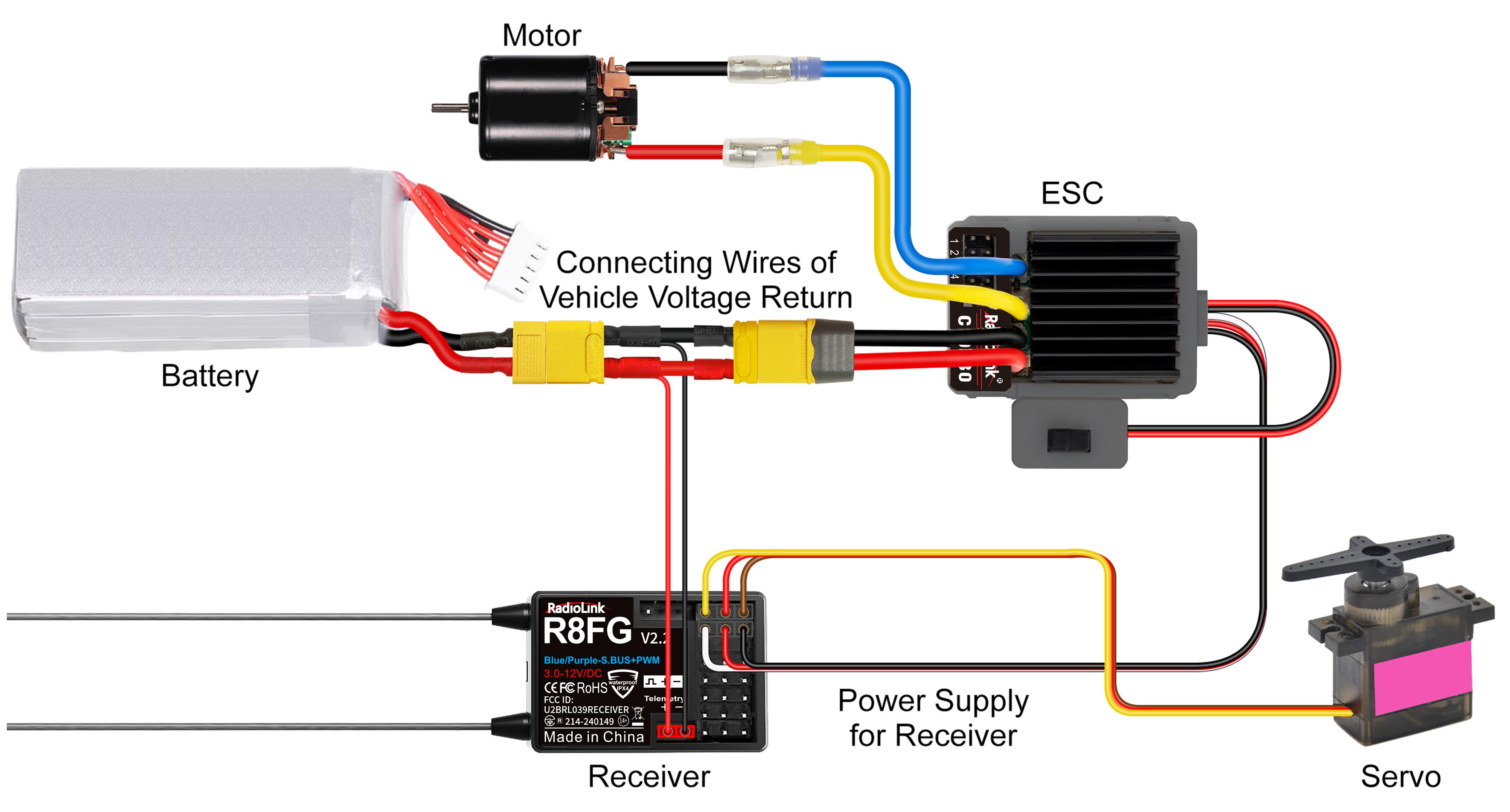
 R8FG supports telemetry of model battery voltage, receiver voltage and RSSI.The model voltage will display by connecting the wire to the ESC, battery, and Telemetry port of receiver R8FG. Telemetry of maximum 8S battery(33.6V) supported.Model battery voltage telemetry can be easily achieved by connecting the male end of the battery wire to ESC while the female end to the battery and the wire with a JST head connects Telemetry (+-) of R8FG as below picture shown. No extra module is needed.Once connect with success, the returned model voltage will be displayed on the screen of RC8P.
Attention:
All channels of the R8FG receiver have electronic anti-reverse insertion function, but the telemetry port of R8FG cannot be reversely connected. Reverse insertion will cause abnormal voltage telemetry. Please strictly follow the picture above to connect the positive and negative poles of the power battery.
Telemetry port is only used to model voltage telemetry. It can not be used to power the receiver.
(3)Low Model Voltage Alarm Setting
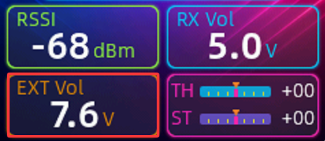
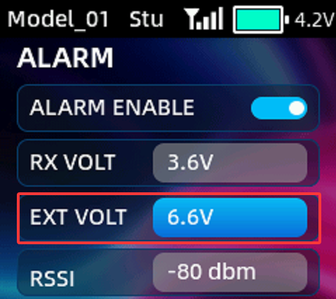 After connecting the telemetry cable as shown above, the model battery voltage will be displayed on the screen of RC8P. Enter the ALARM menu to set the EXT VOLT (as shown on the right). When the model battery voltage is lower than the EXT VOLT, the transmitter will issue an alert. The value of EXT VOLT can be customized based on the battery type and equipment requirements.
1.3.4Working Mode of R8FG
R8FG has a built-in gyroscope, which can output not only PWM signals but also SBUS signals. There are four working modes, including ordinary PWM mode, PWM+SBUS mode, PWM+Gyro mode, and PWM+SBUS+Gyro mode. The channel signal corresponding to each mode are as follows:
R8FG Working Mode | ||||||
Working Mode | PWM Mode | PWM+SBUS Mode | PWM+Gyro mode | PWM+SBUS +Gyro Mode | Note | |
LED Indicator Color | Green | Blue | Red | Blue/Purple | ||
Channel | Telemetry | TELEMETRY port is only for 2S-8S battery voltage telemetry. The port cannot be used to power the receiver. | ||||
1 | PWM | PWM | PWM | PWM | Steering | |
2 | PWM | PWM | PWM | PWM | Throttle | |
3 | PWM | PWM | PWM | PWM | Auxiliary | |
4 | PWM | PWM | PWM | PWM | Auxiliary | |
5 | PWM | PWM | PWM | PWM | Auxiliary | |
6 | PWM | PWM | PWM | PWM | Auxiliary | |
7 | PWM | PWM | PWM | PWM | Auxiliary | |
8 | PWM | S.BUS | PWM | S.BUS | Auxiliary | |
Working mode settings
1.Turn on/off the gyro: Short press the binding button 3 times within 2 seconds to switch the gyro on and off, and the color of the LED indicator will switch accordingly.
2.Gyro phase switch: Short press the binding button twice within 2 seconds to switch the gyro phase.
3.Turning on/off the SBUS: short press the binding button once to turn on/off the SBUS, and the color of the LED indicator will switch accordingly.
R8FG working modes tutorial: https://www.youtube.com/watch?v=uDIiyr9tmYA
1.3.5Gyro Function of R8FG
R8FG has a built-in gyroscope. The integrated high-performance gyro adopts the software filter and PID algorithm, timely and precisely corrects the sensitivity and improve the stability. Its good flexibility to different models and fields easily achieves professional performance even with drift cars.
1)Enable Gyro
Gyro function of R8FG is turned off by default. Since integrated gyro in R8FG will self-check, it is very important to remain R8FG still when powering it on. When red LED is off means NO gyro.
Press binding button three times (interval less than 1 second), the red LED will flash three times, indicating that gyro is enabled.
Attention:Its normal that the servo keeps shake when connect to receiver, but the transmitter have not operated. Because, the gyro will help to correct the steering gear angle of servo automatically if the gyro function has turned on, you can turn off the gyro function if you do not need this function.
If the receiver has not be moved, but the servo keep shake, there are two reasons as below:
① the servo has connect to the SBUS channel of receiver, please reconnect the servo to other PWM channels, because the standard servo only supports PWM signal input.
② the gyro is too much sensitivity, please enter the GYRO menu to set and reduce thegyro sensitivity.
2)Gyro Reverse
Set the gyro forward, turn the car right or left to see whether gyro functions. The wheel will turn left when the car is turned right and the wheel turns right when the car is turned left. If the gyro acts counter, press the binding button twice, the red LED flashes twice, the gyro reverse is corrected.
3)Gyro Sensitivity Setup
Once the gyro function is enabled, the sensitivity can be adjusted on the gyro menu pf RC8P. Users can assign the encoder, VR knob, or DL1 to adjust the gyro sensitivity. 100% represents maximum sensitivity, while 0% indicates zero sensitivity (effectively turning off the gyro). Please refer to the Chapter 2.15 GYRO for detailed information on how to adjust the gyro sensitivity.
1.3.6 Installment of Receiver Antenna
It is important to install the receiver antenna correctly on the model, because wrong receiver antenna installation will cause poor signal quality.
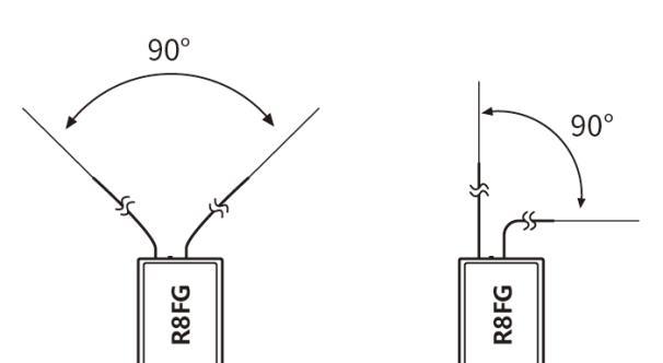 How receiver antenna installation affects signal quality? Here are the common mistakes when installing the antennas:
(1)The two antennas of the receiver CANNOT overlap, because they will interfere with each other.Keep the two antennas at a 90-degree angles, as shown on the right.
(2)Antennas should NOT be placed near metal objects, because reflection of the conductor panel will drastically worsen the signal.
(3)Do NOT keep antennas parallel to the ground. It should be placed vertically to the ground.
(4)Big models may contain metal parts that influence signal emission. In this case. antennas should be positioned at both sides of the model to ensure the best signal status in all circumstances.
(5)Antennas should be kept away from metal conductor and carbon fiber at least half inch away and no over bending.
(6)Keep antennas away from motor, ESC or other possible interference sources.
(7)Sponge or foam material is advised to use to prevent vibration when installing receiver.
(8)Receiver contains some electronic components of high-precision. Be careful to avoid strong vibration and high temperature.
(9)Special vibration-proof material for R/C like foam or rubber cloth is used to pack to protect receiver. Keeping the receiver in a well sealed plastic bag can avoid humidity and dust, which would possibly make the receiver out of control.
Please refer to the below link for more details on how to install the antenna of the receiver:
https://www.radiolink.com/receiver_antenna_installation
1.3.7 RSSI Testing
 If the control distance of cars or boat is short, please refer to this instruction to test the transmitter. This instruction will introduce the test procedure of the transmitter RSSI value and the solution to the abnormal RSSI value.
Turn on the transmitter and power on the receiver at the same time, and then the transmitter and receiver will be connected (if not connected, you need to bind again), the signal tower appears on the transmitter interface, indicating that the binding is successful. The value of RSSI will appears on the homepage, and the RSSI value will keep changing according to the distance between the transmitter and the receiver, as shown on the right.
Make the receiver antenna and transmitter antenna parallel, keep transmitter apart from receiver about 60 centimeters and both antennas straight. It is normal that RSSI value is within the range of 0 to -30dBm. The closer the value is to 0, the stronger the signal is, as shown below.
Abnormal signal strength solution:
Check whether the antennas of the receiver and transmitter are damaged. Most signal strength degradation is caused by antenna damage. If it is damaged, the antenna needs to be replaced. If there is no damage, you can test the transmitter and receiver for malfunctions by replacing the receiver. If still cannot solve the problem, email to after_service@radiolink.com.cn to get support.
Chapter 2 Basic Setting
This chapter introduces all the functions in the menu.
2.1 SYSTEM SETTING
SYSTEM SETTING menu is used to set the system functions listed below:
LANGUAGE
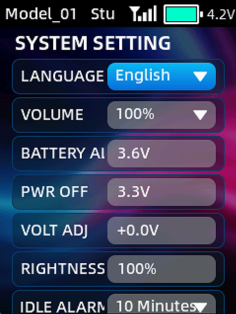 The menu language supports Chinese, English, German, French, Russian, and Japanese.
VOLUME
Volume is to set the volume of the sound. You can set it to 0% (mute), 25%, 50%, 75% and 100%. 100% is the maximum volume.
BATTERY ALARM
Battery alarm is to set alarm voltage for the transmitter battery. When the battery voltage is lower than the alarm voltage, an alarm will sound. Battery alarm defaults to 3.6V.
PWR OFF
Power off voltage. When the voltage of the transmitter reaches the power off voltage, the transmitter will automatically shut down. Power off voltage defaults to 3.3V.
VOLT ADJ
When there is a difference between the battery voltage displayed and the actual battery voltage, you can set voltage adjustment to make the voltage display consistent. The adjustment range is between -5V and +5V.
BRIGHTNESS
Brightness is to set the brightness of the screen. The adjustment range is from 10% to 100%.
IDLE ALARM
Idle alarm is to set the alarm time when there is no operation on the transmitter. When the transmitter is on standby for a long time without operation, an idle alarm can be set to remind the user to avoid over-discharging of the battery caused by long-term standby. The maximum idle time is one hour.
BACKLIGHT TIME
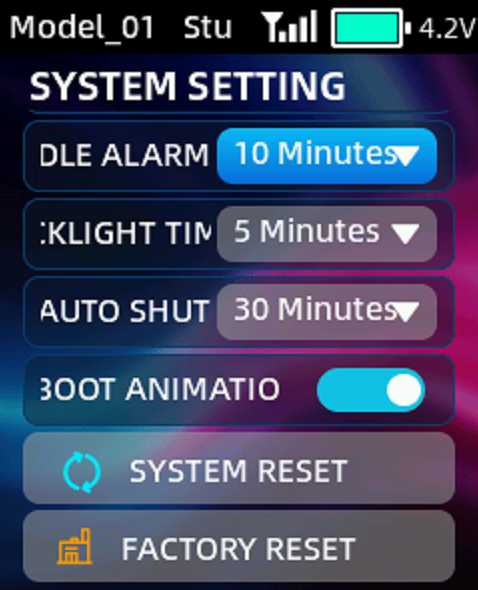 Backlight time is to set the time of the backlight, namely how long the screen stays on when there is no operation. NULL means the screen won’t go off when there is no operation for a long time. The maximum backlight time is one hour.
AUTO SHUTDOWN
The time of auto shutdown, namely how long the transmitter will turn off automatically when there is no operation. NULL means transmitter won’t turn off automatically when there is no operation for a long time. The maximum auto shutdown time is one hour.
BOOT ANIMATION
This setting is used to turns on/off the startup animation.
SYSTEM RESET
All parameters in the "System Settings" menu except "Language" can be reset.
Click "SYSTEM RESET", the screen will prompt "Are you sure to reset system?". Select "Yes" and the system settings are reset
FACTORY RESET
All parameters of the transmitter can be reset, except "Language", including system setting parameters and all model data.
Note: If you just need to clear the current model parameters, please reset the current model in the MODEL menu in Transmitter Settings. Factory reset here will clear all model data. Once the model data is cleared, it cannot be restored, so please use this function with caution!
Click "Factory Reset" and a prompt will appear on the screen asking if you need to reset factory settings. Select "Yes" and wait for about a minute to reset all the settings.
2.2 MODEL
The MODEL menu is used for model management, including model select, mode copy/paste, rename and model reset.
RC8P can store up to 30 sets of model data, and you can select the model you want at any time.
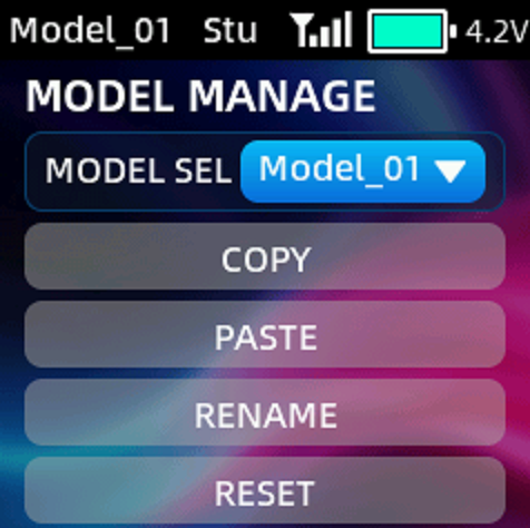 COPY/PASTE: When a new model is the same or similar to a previously used model, you can use this function to copy it in order to quickly complete the settings.
For example, if you need to copy the data of model 1 to model 2, you can select model 1 and click copy, then select model 2 and click paste. Please note: When copying a new model, the name of the original model will also be copied. You need to distinguish and rename the new model to avoid confusion.
RENAME: You can write and change the model name for the selected model.
RESET: Model reset is to clear all the settings of the current model and restores the current model to default values.
 2.3 REVERSE
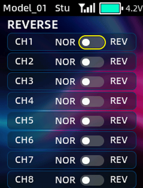
You can perform the reverse processing of the output data of one channel or more channels. This function is used in the debugging of a model.
Models may follow different standards in the design. In the assembly and debugging of a model, if you find that the operation model is opposite to the required direction, for example, the model goes to the left when you want the right direction, the output signal direction of the transmitter needs to be adjusted at this time. The function is used to adjust the action direction of output signals of each channel.
 Move the cursor to the channel that needs to be modified, and short press the scroll key to switch the direction.
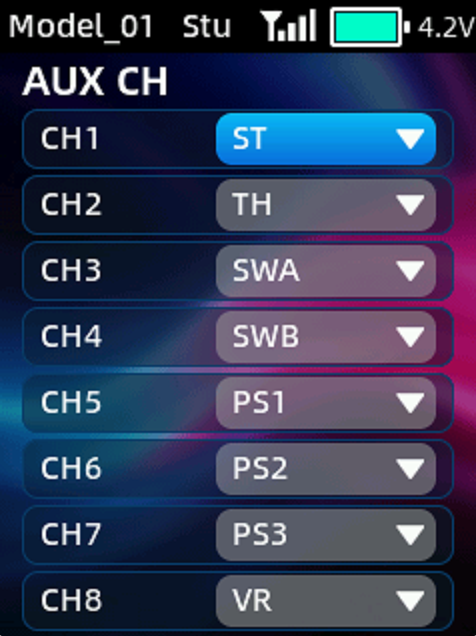
2.4 AUX CH
AUX CH function is used to assign the control switches for CH1 to CH8. You can set ST (steering wheel), TH (throttle trigger), SWA, SWB, VR, PS1, PS2, PS3 and DL1。
NULL means no switch assigned.
2.5 SW AUDIO
 This function can be used to set the voice broadcast function of SWA, SWB, PS1, PS2, PS3 and TH (throttle trigger). When users assign these switches to control a certain function, they can set the switch to broadcast different voices at different positions. The function is often used to broadcast the on or off of a certain function.
Users can customize the voice switch. Just copy their voice file to the transmitter. For voice production methods, please refer to Chapter 4 Customized Switch Audio Production.
2.6 END POINTS
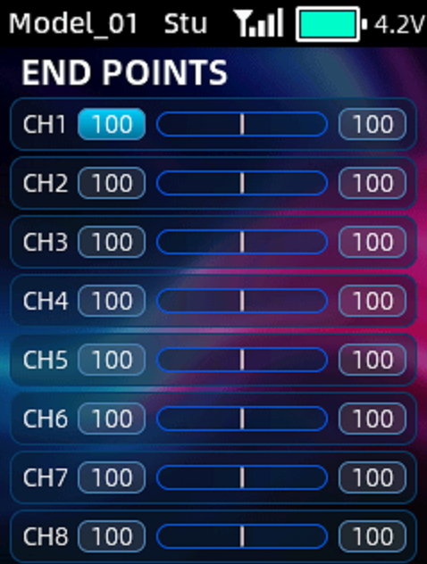 Adjust the travel amount of the servo output. This function is used in debug, and can be used to set the travel amount at both ends of the channel respectively.
When the model is designed, there are changes in the size of the structure and the specification may not be unified. In addition, there may be different sizes of operator's habitual actions. The servo travel function can be used to set the travel amount required for each channel to adjust the corresponding structure for the best match, to obtain the required operation effect. For example, you want to operate that the turning action is not so large, you can adjust the value of the direction channel at both ends to be smaller. In this way, the turning action should be smaller, with less likely to be tailspin.
The end points can be set from 0 to 120 for each channel.
2.7 RF SETTING
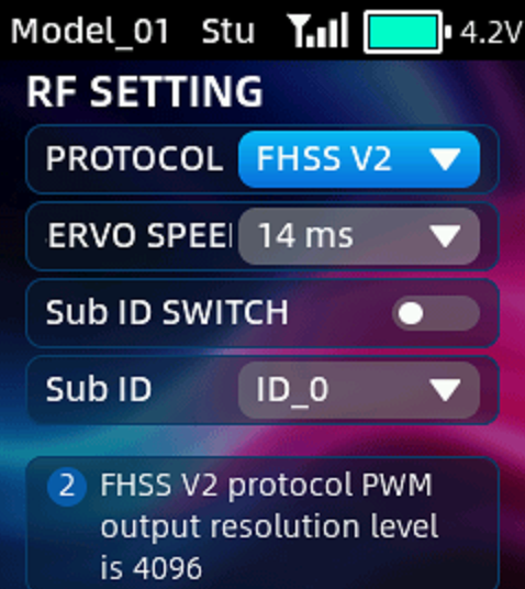 The function is to set the receiver protocol and servo speed.
PROTOCOL: The protocol of the receiver. FHSS V1 and FHSS V2 can be selected.
SERVO SPEED: Servo response speed. After FHSS V2 is selected, servo speed can be set. 14ms, 4ms, and 3ms can be selected. 14ms is the response speed of the analog servo. 4ms and 3ms are the response speeds of the digital servo. If you are using a digital servo, you can select a servo speed of 4ms or 3ms. Please confirm whether the receiver you are using supports digital servo.
For the differences of the protocols and servo speed, please refer to the table below:
Protocol | PWM Output Resolution | Servo Output | Compatible Receiver |
FHSS V1 | 2048 | 14ms | All receivers compatible with RC8P |
FHSS V2 | 4096 | 3ms/4ms/14ms available | R16F, R16SM, R12F, R12FL, R8FGH, R8FG V2.1 and later versions, R4FGM V2.1 and later versions, R8FG and R4FGM receivers with a factory date of 2023/4/26 or later |
After switching protocols, please re-bind the receiver and the transmitter. | |||
2.8 Sub ID
RC8P can be bound with multiple receivers. When RC8P and multiple receivers have been bound successfully, and RC8P and all successfully paired devices are turned on at the same time. There are two ways to use them:
1. When Sub ID function is turned off, RC8P can control multiple devices at the same time.
2. When Sub ID function is turned on, RC8P can control the specified device according to the selected Sub ID. RC8P has 16 groups of Sub ID functions, and each ID corresponds to a receiver. Set the Sub ID first. When all the devices are turned on, you can control one of the devices through the Sub ID function. At this time, the other devices are on standby.
For example: Bind RC8P with a truck and a car and turn all them on. First, use RC8P to control the car to run to the bucket of the truck, and then switch the receiver ID on the truck to drag the car back to the destination.
Sub ID function setting steps:
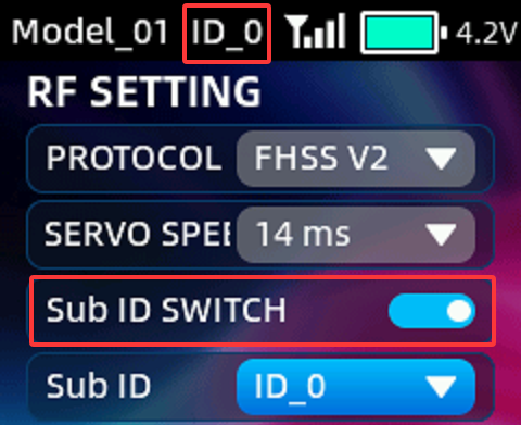 1.Turn on Sub ID switch. Select the Sub ID number according to your models, bind them and set the parameters.
2.Once the Sub ID switch is turned on, the corresponding ID number will be displayed on the top taskbar (If the trainer function, condition function, and Sub-ID function are all enabled, they will be displayed alternately in the top taskbar). Then you can control the corresponding model.
2.9 ALARM
The function is used to set alarms for RSSI, receiver voltage and external battery voltage.
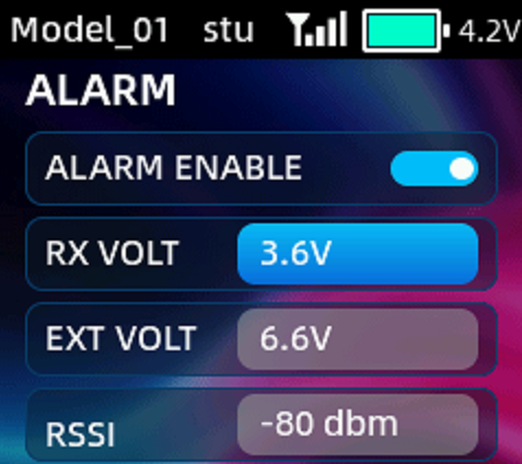 RX VOL ALARM: When the receiver voltage reaches the receiver voltage alarm value, the transmitter will issue an alarm. It defaults to 3.6V. This value can be customized according to operational requirements.
EXT VOL ALARM: When the external battery voltage reaches the external battery voltage alarm value, the transmitter will issue an alarm. It defaults to 6.6V. This value can be customized according to operational requirements.
RSSI: The alarm of received signal strength indicator. When the RSSI value reaches the RSSI alarm value, the transmitter will issue an alarm. The default value is -80dbm. The specific alarm value can be set based on the control range you want.
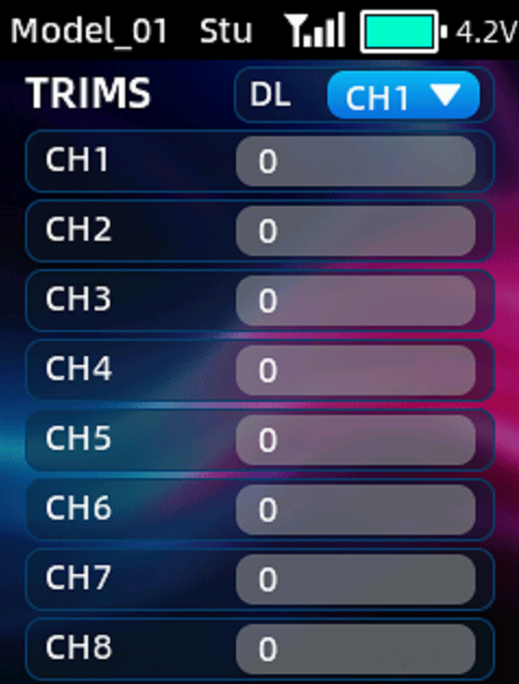
2.10 TRIMS
The function is used to correct mechanical errors, and adjust the neutral position of each channel. The trim of each channel defaults to 0. The adjustable range is from -100 to 100.
DL: Once a channel is selected, the DL1 code switch can be used to adjust the trim of this channel.
2.11 FAIL SAFE
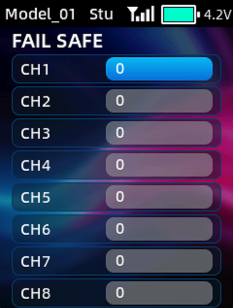 This function sets the servo operation position when transmitter signals cannot be received by the receiver for some reason. Channel 1 (Steering) and Channel 2 (Throttle) are set to a default value of 0. This means that if the receiver loses signal, the throttle will stop to output while the steering servo holds its last commanded position to prevent damage to the vehicle or model. The adjustable range for this setting is -120 to +120. If you modify the fail safe of the throttle—setting it to something other than 0—the throttle channel will automatically output that specific, fixed throttle value when the signal is lost. This could potentially cause the model to continue moving forward or backward uncontrollably after losing signal; therefore, please exercise extreme caution when modifying the fail safe value for this channel.
2.12 CH SPEED
CH SPEED (channel speed) function can be used to adjust the output speed of some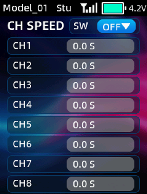 channels for a specific model. For example, if you want a crane's boom to rise or lower slowly during operation, you can achieve this by slowing down the output speed of the corresponding channel.
SWITCH: A switch can be set to control the CH SPEED function. It can be set to OFF/ON to keep the function disabled/enabled, or it be assigned to a physical switch for control. Optional switches include SWA, SWB, PS1, PS2 and PS3.
Channel speed defaults to 0 seconds, which means no channel delay. Channel speed can be set up to 10 seconds, which means it takes 10 seconds to travel from the minimum to the maximum servo output.
2.13 CHANNEL HOLD
Channel hold function can set the channel output to a fixed value. When the channel hold is turned on, the channel output will jump to the locked position regardless of the current switch position. For example, when using a crawler, you can activate the channel hold for the throttle channel (Channel 2) with a switch, and the crawler can maintain a constant speed without touching the trigger—effectively acting as a cruise control function.
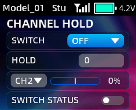 SWITCH: A switch can be set to control the channel hold function. It can be set to OFF/ON to keep the function disabled/enabled, or it can be assigned to a physical switch for control. Optional switches include SWA, SWB, PS1, PS2 and PS3.
HOLD: Fixed output value of the channel. The setting range is from -100 to +100. The positive and negative values represent the opposite direction of the servo.
CH1-8: The channel that is locked. The servo bar on the right allows you to view the output value for that channel.
SWITCH STATUS: Display whether the channel hold function is currently enabled or disabled.
2.14 CONDITIONS
Three conditions can be set in a model
COND 1/COND 2/COND 3: SWA and SWB can be selected to control the conditions. When multiple switches are used to switch conditions, the condition priority is 3>2>1.
A list of functions can be turned on or off by using conditional switches, including GYRO, END POINTS, BRAKE CURVE, RF SETTING, STEERING CURVE, TH SPEED, ABS and THROTTLE CURVE. If you need to use conditional switches to control the above functions, the corresponding functions on this interface need to be turned on, otherwise the conditional switches will not take effect.
For example: if users needs to use one switch to control 3 different throttle curves, please set it as these steps below:
(1) Set the switches of COND 1/2/3 to SWA↑/SWA-/SWA↓ respectively;
(2) Turn on THROTTLE CURVE function on the interface;
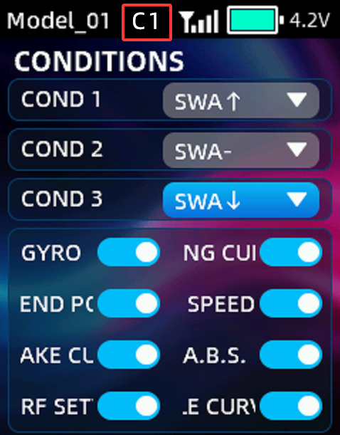 (3) Enter the throttle curve setting interface under the advanced settings menu, push SWA up, which is condition 1, and set the first throttle curve; push SWA to the middle, which is condition 2, and set the second throttle curve; push SWA down, which is condition 3, and set it to the third throttle curve. Flip the SWA to switch between different throttle curves. When the SWA condition switch is placed in different positions, the top taskbar will also display the corresponding condition number (If the trainer function, condition function, and Sub-ID function are all enabled, they will be displayed alternately in the top taskbar).
2.15 GYRO
The function is used to adjust the gyroscope sensitivity. When adjusting the gyro sensitivity, please make sure the receiver has a built-in gyroscope and the gyroscope function of the receiver is turned on.
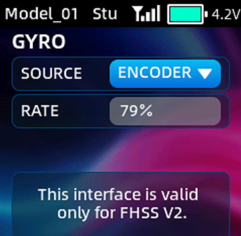 SOURCE: Encoder(Scroll key), VR knob and DL1 code switch can be used to adjust the gyroscope sensitivity.
RATE: The sensitivity can be set from 0% to 100%. 100% means the strongest sensitivity, while 0% means the gyroscope is turned off.
Note: GYRO function is only applicable to FHSS V2 protocol receivers, including R8FGH, R8FG V2.1 and later versions, R4FGM V2.1 and later versions, R8FG and R4FGM receivers with a factory date of 2023/4/26 or later. When using receivers of FHSS V1 protocol (such as R7FG and R6FG), the GYRO setting menu is ineffective. To adjust sensitivity, please first enter the END POINTS settings menu and set the end points of CH8 to 120 on both sides. Then enter the AUX CH menu and assign the switch of CH8 to the knob switch such as VR and DL1 to adjust the sensitivity.
2.16 STEERING CURVE
This function is used to change the sensitivity of the steering servo, making its action changes linear or non-linear.
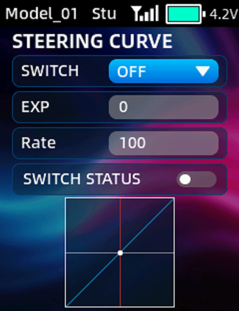 SWITCH: A switch can be set to control the steering curve function. It can be set to OFF/ON to keep the function disabled/enabled, or it can be assigned to a physical switch for control. Optional switches include SWA, SWB, PS1, PS2 and PS3.
EXP: Adjusts the sensitivity of the steering servo. When the curve is set to a negative value, a larger negative value results in lower sensitivity of the steering wheels near the neutral position and higher sensitivity at the ends. Conversely, when the curve is set to a positive value, a larger positive value results in higher sensitivity near the neutral position and lower sensitivity at the ends. The adjustable range for EXP is from -100 to +100.
Rate: The ratio of the actual steering servo output value to the original value. For example, when the rate is set to 50, the actualoutput value of the steering channel is 50%. The rate can be set in the range from -100 to +100, and the plus and minus represent the opposite directions of the servo.
SWITCH STATUS: Display whether the steering curve function is currently enabled or disabled.
2.17 THROTTLE CURVE
This function is used to change the sensitivity of the throttle, making its action changes linear or non-linear.
SWITCH: A switch can be set to control the throttle curve function. It can be set to OFF/ON to keep the function disabled/enabled, or it can be assigned to a physical switch for control. Optional switches include SWA, SWB, PS1, PS2 and PS3.
TYPE: EXP and CRV are available. EXP curve features a curved increase in control, while the CRV is a multi-point curve.
EXP:
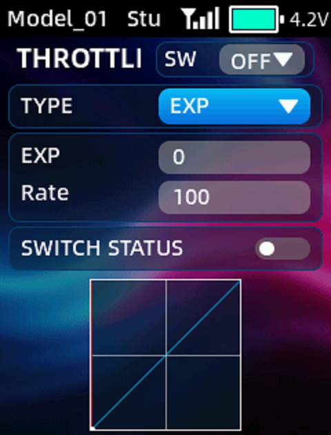 EXP: Adjust the sensitivity of the throttle from the lowest point to the highest point. When the curve is set to a negative value, the greater the negative value, the lower the sensitivity of the joystick at lowest throttle, and the higher the sensitivity at highest throttle; When the curve is set to a positive value, the positive value, the larger it is, the more sensitive the joystick is at lowest throttle and the less sensitive it is at highest throttle. The settable range of the curve is from -100 to +100.
Rate: The ratio of the actual output value of the throttle channel to its original value. For example, when the rate is set to 50, the actual output value of the throttle channel is 50%. The adjustable range for the rate is from 0 to 100.
CRV:
Set a 5-point curve type from the lowest point to the highest point of the throttle. For example, if point 1 is 0, it means that the travel amount of point 1 is 0; if point 2 is 25, it means that the travel amount of point 2 is 25. The output value of each point is the marked 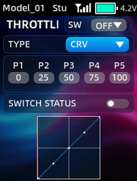 position of this point.
SWITCH STATUS: Display whether the throttle curve function is currently enabled or disabled.
2.18 BRAKE CURVE
This function is used to change the sensitivity of the brake, making its action changes linear or non-linear.
SWITCH: A switch can be set to control the brake curve function. It can be set to OFF/ON to keep the function disabled/enabled, or it can be assigned to a physical switch for control. Optional switches include SWA, SWB, PS1, PS2 and PS3.
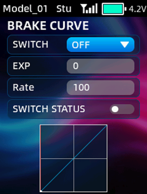 EXP: Adjusts the sensitivity of the brake. When the curve is set to a negative value, the more negative the value, the lower the sensitivity at the initial stage of braking and the higher the sensitivity at the final stage. Conversely, when the curve is set to a positive value, the more positive the value, the higher the sensitivity at the initial stage of braking and the lower the sensitivity at the final stage. The adjustable range for EXP is from -100 to +100.
Rate: The ratio of the actual output value of the brake to the original servo value. For example, when the rate is set to 50, the actual output value of the brake is 50%. The adjustable range for Rate is from 0 to 100.
SWITCH STATUS: Display whether the brake curve function is currently enabled or disabled.
2.19 A.B.S.
A.B.S. is the pulse brake to prevent the tires from completely locking up during deceleration—a condition that would result in a loss of effective directional control. A.B.S. function can minimize the duration of any loss of control and facilitates a smoother, more gradual transition in vehicle angle.
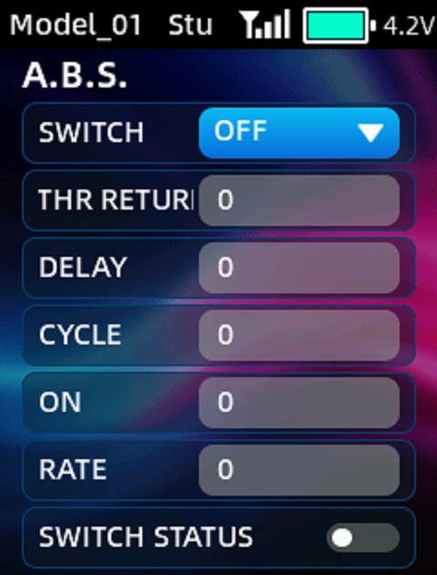 SWITCH: A switch can be set to control the A.B.S. function. It can be set to OFF/ON to keep the function disabled/enabled, or it can be assigned to a physical switch for control. Optional switches include SWA, SWB, PS1, PS2 and PS3.
THR RETURN: Amount of brake return. When set to 0, the ABS function is not performed. When set to 50, the servo returns 50% (1/2) of the trigger operation amount and when set to 100, the servo returns to the neutral position. THR RETURN is influenced by the RATE on the brake curve function.
DELAY: Delay Amount. Sets the delay between the initiation of braking and the activation of the A.B.S. function. When set to 0, the A.B.S. function activates immediately; at 50, it activates after a delay of approximately 0.7 seconds; at 100, it activates after a delay of 1.4 seconds.
CYCLE: Intermittent Interval. The higher the cycle setting, the longer the time interval between consecutive intermittent braking pulses. Conversely, the lower the setting value, the shorter the interval between pulses.
ON: The trigger position at which the A.B.S. begins.
RATE: The proportional relationship between the brake activation time and the cycle. For example, when the ratio is set to +3, the braking action is executed more rapidly—specifically, the brake application time is longer while the release time is shorter; conversely, when set to -3, the release time is longer while the application time is shorter.
SWITCH STATUS: Display whether the A.B.S. function is currently enabled or disabled.
2.20 PROGRAMMABLE MIX
RC8P provides 4 groups of mixing, which can control two channels simultaneously with one switch.
MIX SELECT: 4 groups of mixing can be set independently, with each set assignable to a specific switch for control.
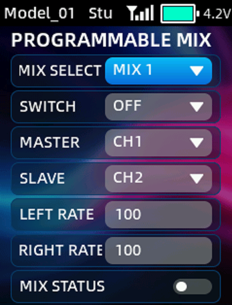 SWITCH: A switch can be set to control the mix function. It can be set to OFF/ON to keep the mix disabled/enabled, or it can be assigned to a physical switch for control. Optional switches include SWA, SWB, PS1, PS2 and PS3.
MASTER: Master channel that controls the slave channel.
SLAVE: Slave channel that is controlled by the master channel.
LEFT RATE: To adjust the end point ratio on the left side of the slave channel. For example, if the LEFT RATE is set to 50, when operating the master channel, the end point of the slave channel on the left side is only 50% of the master channel. The adjustment range is from -100 to 100. A positive number indicates that the slave channel and the master channel move in the same direction, and a negative number indicates that the slave channel and the master channel move in opposite directions.
RIGHT RATE: To adjust the end point ratio on the right side of the slave channel. For example, if the RIGHT RATE is set to 50, when operating the master channel, the end point of the slave channel on the right side is only 50% of the master channel. The adjustment range is between -100 and 100. A positive number indicates that the slave channel and the master channel move in the same direction, and a negative number indicates that the slave channel and the master channel move in opposite directions.
MIX STATUS: Display whether the mix function is currently enabled or disabled.
2.21 TRAINER
SWITCH: A switch can be used to enable or disable PPM signal input or output via the Type-C port of RC8P. It can be set to OFF or ON to keep the PPM signal disabled or enabled, or it can be assigned to a physical switch for control. Optional switches include SWA, SWB, PS1, PS2 and PS3.
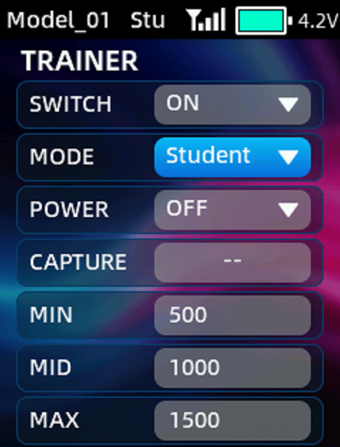 Modes: Three modes are available, including: head track mode, trainer mode, and student mode. When the trainer function is enabled, the current mode ill be displayed in the top taskbar (If the trainer function, condition function, and Sub-ID function are all enabled, they will be displayed alternately in the top taskbar).
---Head track mode: Typically used for head track input.
---Trainer mode: When RC8P is used as a coach transmitter, set trainer mode to control the model alternately with the student transmitter.
---Student mode: When RC8P is used as a student transmitter, set student mode.
POWER: This option can be configured when RC8P is used as a coach transmitter with a RadioLink wireless trainer cable. ON means the Type-C port can supply power to the receiver of the student transmitter. OFF means the Type-C port doesn’t supply power. When using the trainer function, set POWER to "ON," and the power button will light up blue.
CAPTURE: Displays the detected PPM input value for Channel 1 every 200ms; "--" is displayed when no valid PPM signal is detected. In trainer mode, the "CAPTURE" value allows you to monitor the PPM input from the student transmitter. By moving the channel 1 switch of the student transmitter, you can adjust the MIN/MID/MAX below to make RC8P compatible with the student transmitter. In head track mode, the "CAPTURE" value serves only to confirm that the head-track device is correctly outputting a PPM signal and acts as a reference for setting the "MID" below.
MIN/MID/MAX: To adjust the pulse width of PPM input and output. Due to the compatibility of different head track or trainer devices, when the PPM neutral point, maximum value, and minimum value cannot correspond, you can modify the MIN/MID/MAX here.
2.22 CALIBRATION
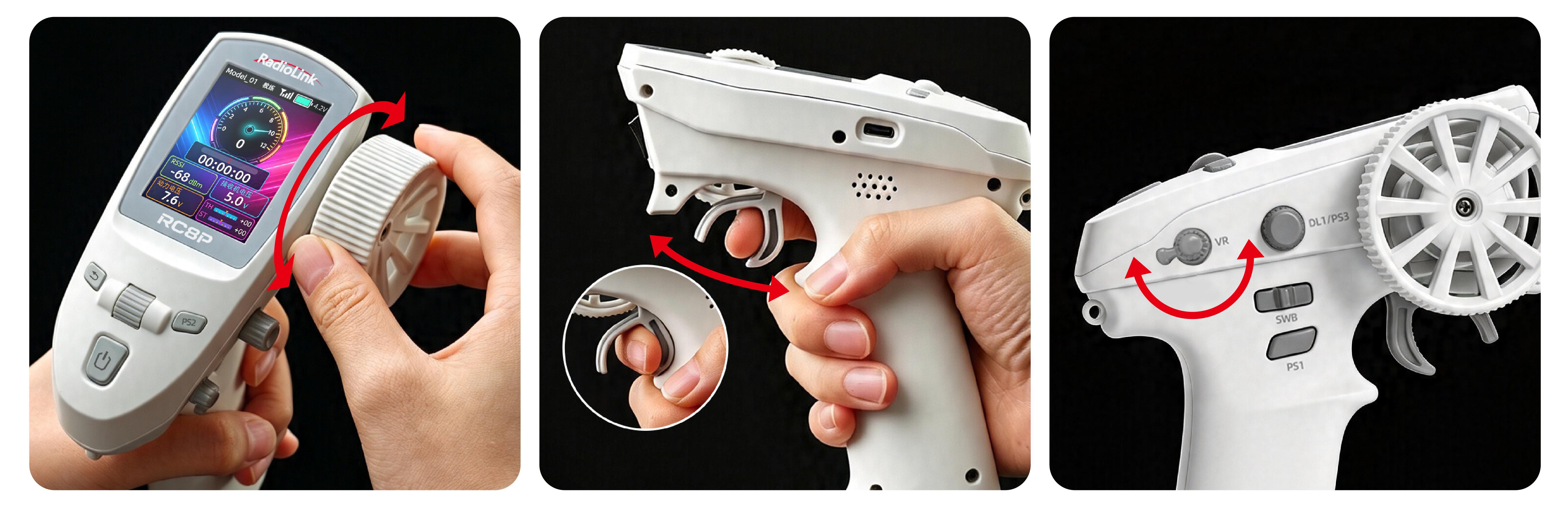
Wheel, trigger, and VR knob correction can be applied when a mechanical offset has occurred for some reason. RC8P calibration tutorial: https://www.youtube.com/watch?v=_6c3HnVPI88
Here are the joystick calibration methods:
1.Short press the scroll key to start the calibration;
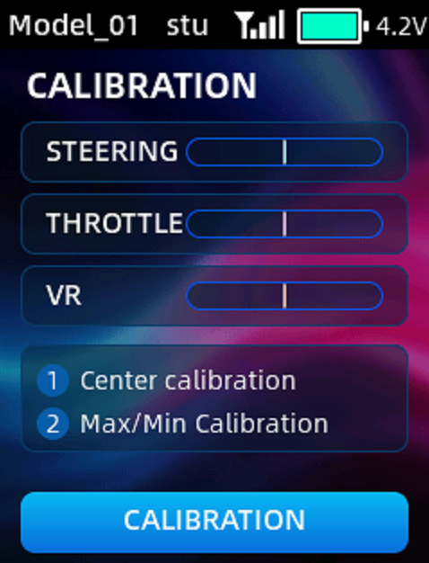
2.Center calibration: Return the steering wheel and throttle trigger to their neutral positions and turn the VR knob to the midpoint so that the servo values for steering, throttle, and VR are all at the center point. Then short press the scroll key to the next step;
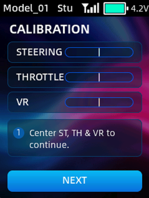
3.Max/Min calibration: Turn the steering wheel clockwise to the end, and then counterclockwise to the end, then let it back to neutral automatically; Pull the throttle trigger to full throttle and the brake position, then let it go back to neutral automatically; Turn the Rotary knob clockwise to the end, and then counterclockwise to the end. Once all steps are complete, short press the scroll key to confirm;
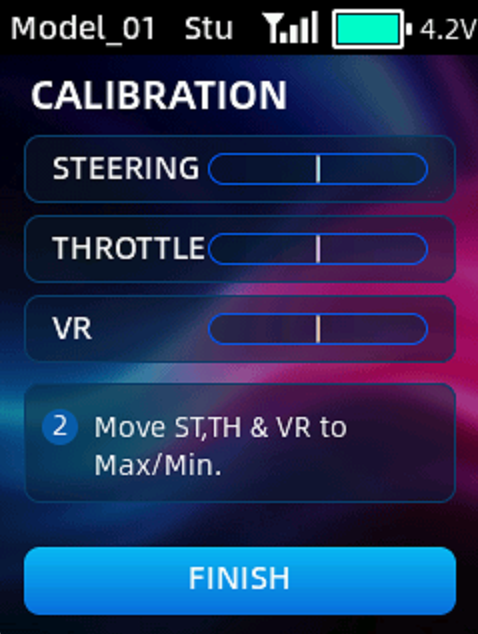
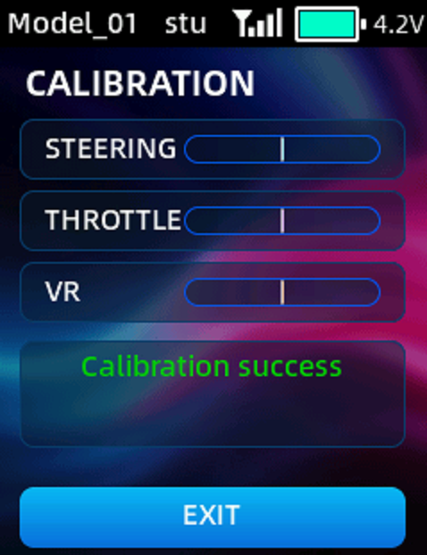
4.After successful calibration, short press the scroll key to exit.
2.23 TIMER
Timer display and settings.
TYPE: There are two modes available, including UP and DOWN. UP: The timing starts from 0. DOWN: The timer starts counting down from the set time.
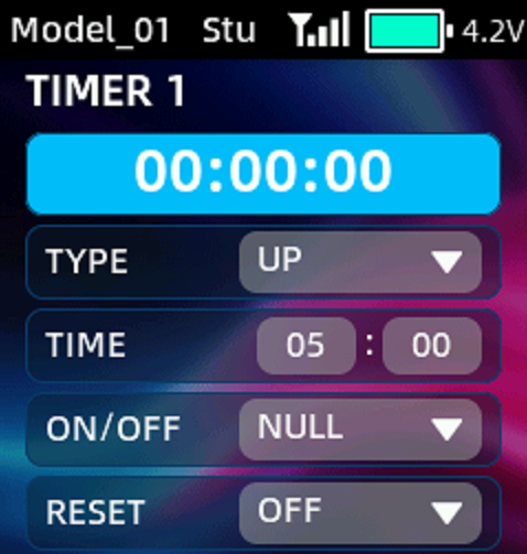 TIME: Alarm time. If the TYPE is set to UP, RC8P will trigger an alarm when the timing time reaches the time set here; If the TYPE is set to DOWN, the timer will count down from the time set here, and RC8P will trigger an alarm when the timing time reaches zero.
ON/OFF: A switch can be set to start or stop the timer. It can be set to OFF/ON to disable/enable the timer, or it can be assigned to a physical switch for control. Optional switches include SWA, SWB, PS1, PS2, PS3 and THR (throttle trigger). When the throttle trigger is used to start or stop the timer, THR HOLD must be configured. The timer starts when the throttle value exceeds the THR HOLD value and stops when it falls below the THR HOLD value.
RESET: A switch can be used for timing reset. It can be set to OFF/ON to disable/enable the reset, or it can be assigned to a physical switch for reset. Optional switches include SWA, SWB, PS1, PS2 and PS3.
2.24 SENSOR BROADCAST
This function can be used to set the voice broadcast of telemetry information, including RSSI, RX Vol (receiver voltage), EXT Vol (external voltage) and BAT Vol(transmitter voltage).
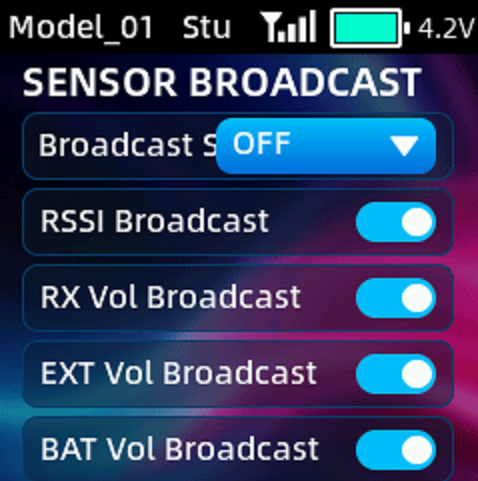 The broadcast switch can be set to SWA, SWB, PS1, PS2 and PS3. OFF means voice broadcast is turned off.
There is an option to turn it on or off, which is used to select whether to broadcast the current telemetry information. A white dot on the left indicates off, and the dot on the right indicates on.
For example: If you set the broadcast switch to SWA↑, push SWA up and the transmitter will broadcast RSSI, receiver voltage, external voltage and transmitter voltage in sequence.
2.25 SWITCH SETTING
This function allows the PS1, PS2, and PS3 buttons to be configured as momentary, latching, or three-position switches.
Momentary: When PS1/PS2/PS3 is pressed, the travel amount is at its maximum (or minimum), and when PS1/PS2/PS3 is released, the travel amount snaps to the minimum (or maximum).
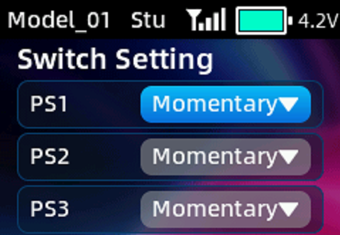 Latching: PS1, PS2, and PS3 buttons work as 2 position switches. Press PS1/PS2/PS3 once, the travel amount is at its maximum (or minimum); Press PS1/PS2/PS3 once again, the travel amount snaps to the minimum (or maximum).
Three-position: PS1, PS2, and PS3 buttons work as 3 position switches. Press PS1/PS2/PS3 once, the travel amount is at its maximum (or minimum); Press PS1/PS2/PS3 again, the travel amount is at 0 position; Press PS1/PS2/PS3 a third time, the travel amount snaps to the minimum (or maximum).
2.26LIGHT CONTROL
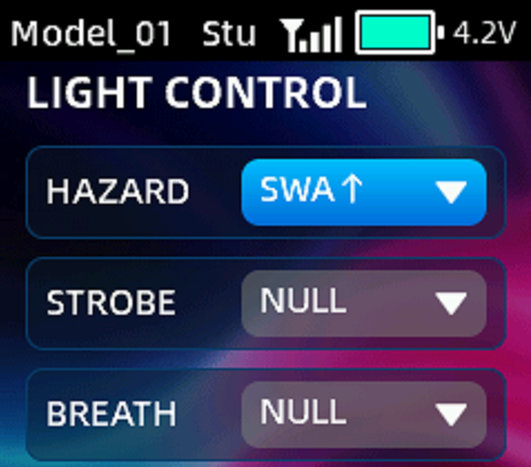 The light control function is only compatible with RadioLink R12FL light control receiver. Bind R12FL to RC8P by selecting FHSS V2 protocol, connect the lights to the corresponding output channels on R12FL, and select a switch on the light control menu. Then you can use the assigned switch to activate or deactivate the corresponding lighting mode.
The switches available for light control function include SWA, SWB, PS1, PS2, and PS3. "NULL" indicates that no switch is assigned. For example, assigning hazard lights to "SWA↑" means the hazard lights will be activated when SWA is pushed up. You may select a different switch based on your personal operating preferences.
Chapter 3 Firmware Update
RC8P will keep updating the firmware to add new functions or optimize the current functions.
RC8P firmware update tutorial: https://www.youtube.com/watch?v=j0kLmJ62wHA
Here are the steps to update the firmware of RC8P:
1.Download the latest firmware package
Download the latest firmware package from https://www.radiolink.com/rc8p_firmware
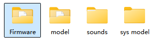 Note: The upgrade package downloaded from the official website is a ZIP file. After downloading it to your computer, you must unzip the file first. The unzipped files contains a "Firmware" folder holding the latest firmware in Mac format. Additionally, in addition to a "Firmware" folder, some upgrade packages may also contain a "sounds" folder—used for storing audio files.
2.Prepare the transmitter
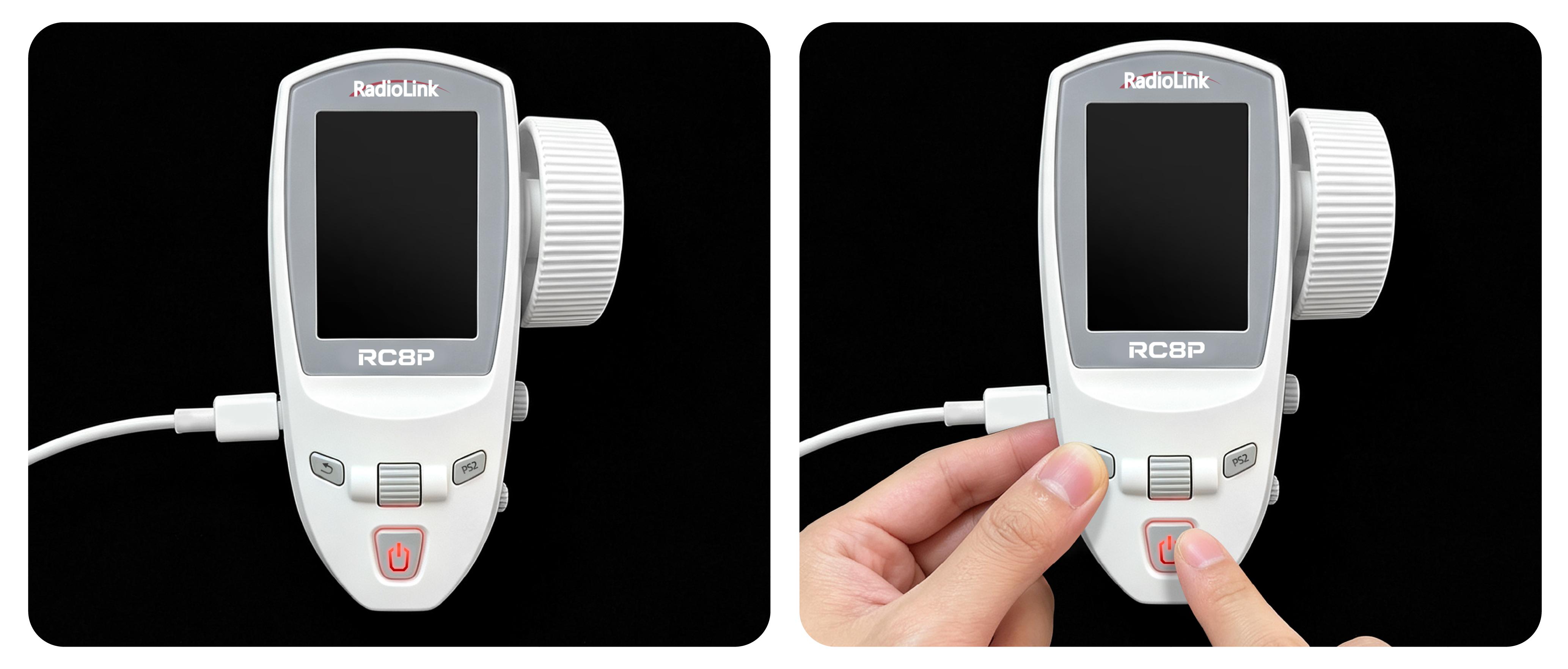
With RC8P transmitter powered off, connect RC8P to the computer using the Type-C cable that comes with it;
Press and hold the Return button while simultaneously pressing and holding the Power button to turn on RC8P;
3.Enter USB mode
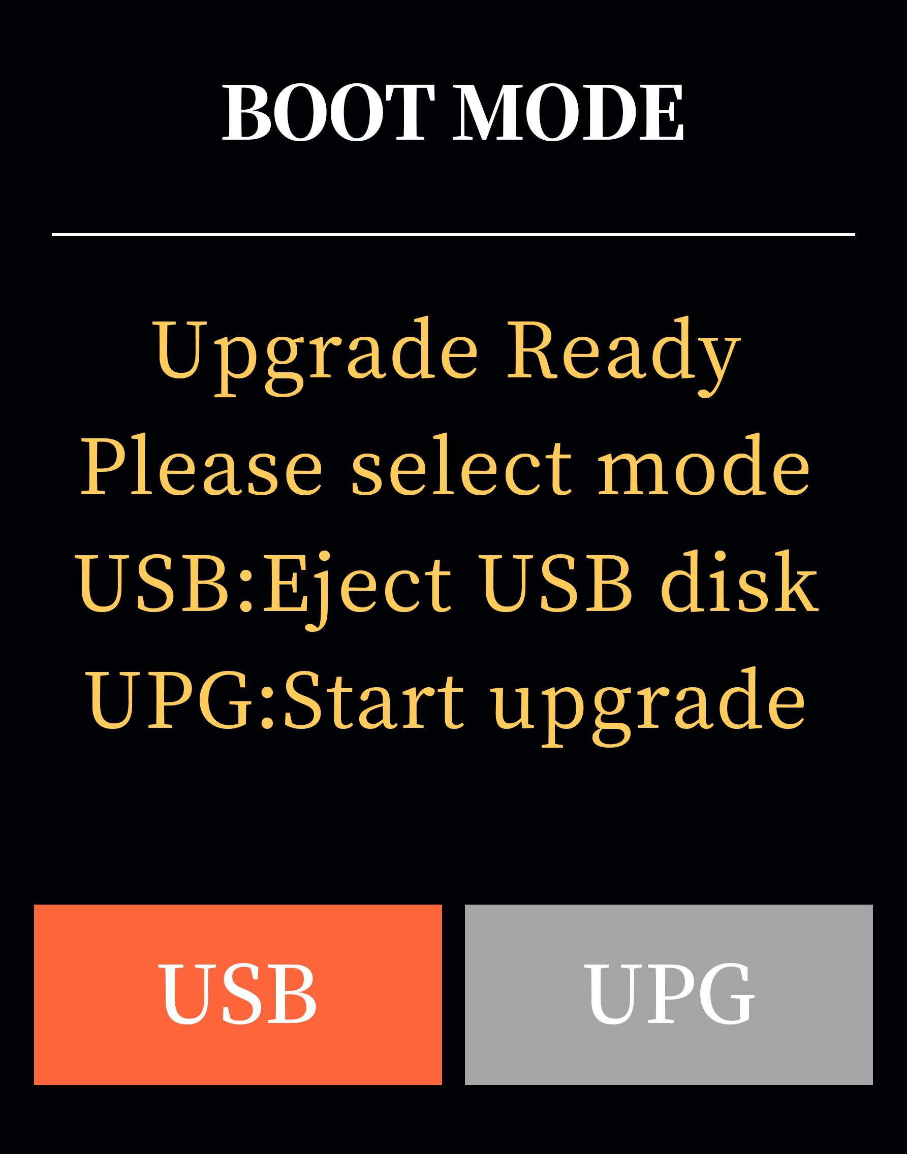
The following BOOT MODE interface will appear on the screen of the transmitter. Select "USB" and press the scroll key to confirm;
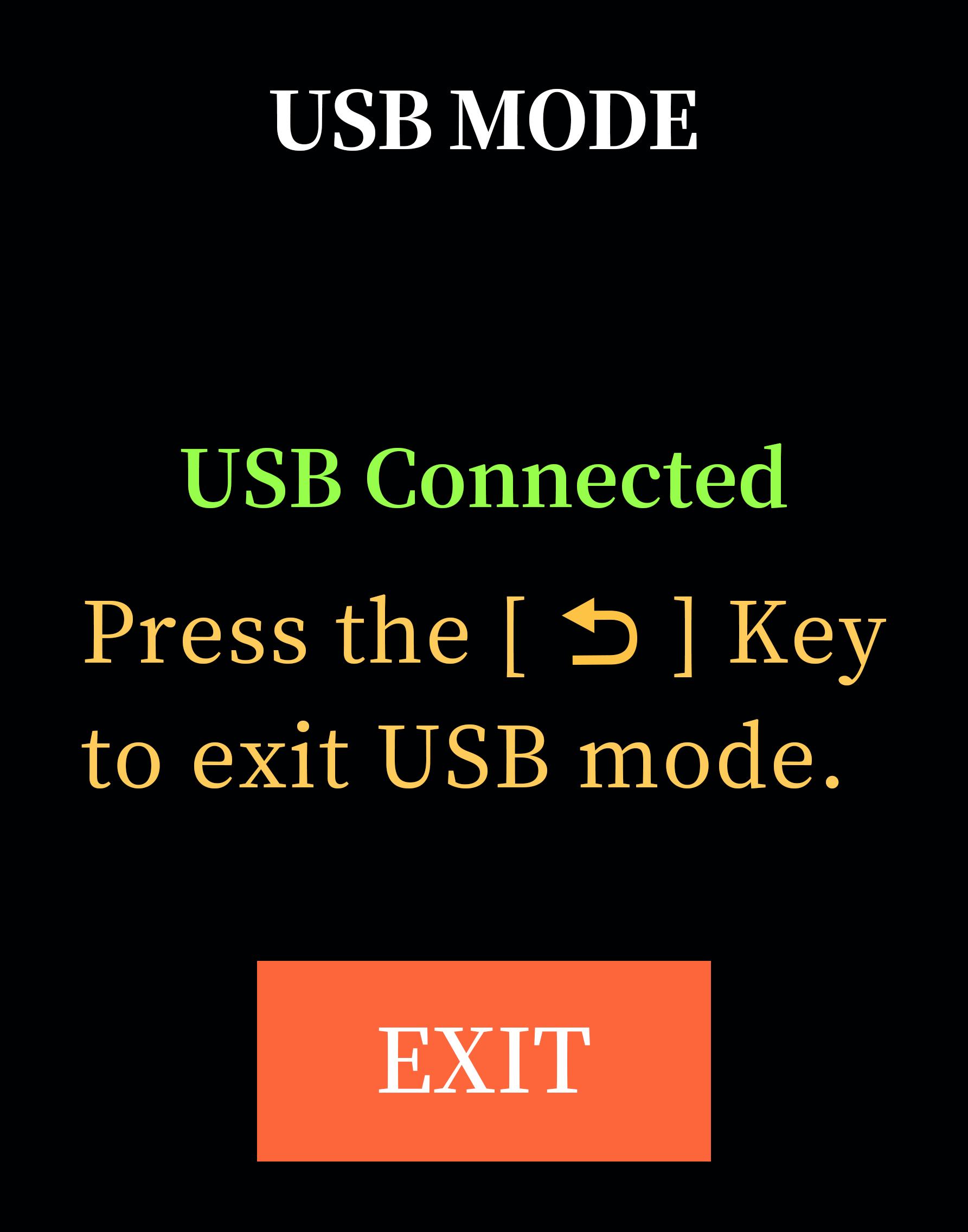
The following USB MODE interface will appear on the screen, indicating that it has entered USB mode, and the computer will recognize the disk of RC8P;
4.Copy the firmware
The computer will display the removable disk of RC8P. Open this disk, and you will see the following four folders. Delete the old firmware from the "Firmware" folder and copy the new firmware into the "Firmware" folder.
Note: If the upgrade package also contains a "sounds" folder, please first back up user-customized audio files to your computer. Then, delete the old audio files from the "sounds" folder, copy the new audio files from the upgrade package's "sounds" folder into the "sounds" folder, and finally, copy your backed-up custom audio files back into the "sounds" folder of RC8P. If you have not created any custom audio files, you can simply delete the old "sounds" folder and copy the new one.
5.Enter Upgrade mode
After the firmware copy is complete, short press the Return button or scroll key to exit USB mode;
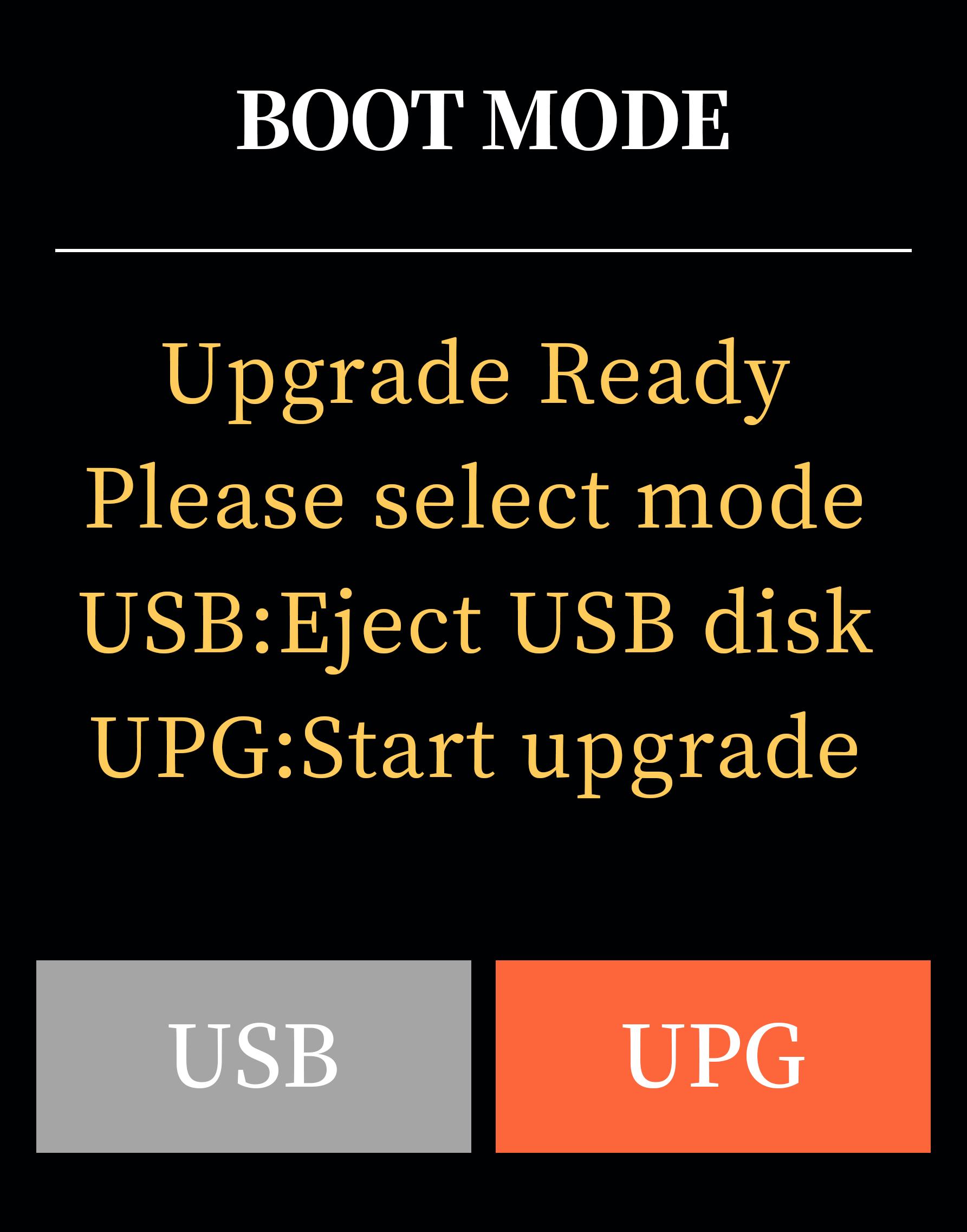
The following BOOT MODE interface will appear on the screen. Select "UPG" and press the scroll key to confirm;
6.Upgrade firmware
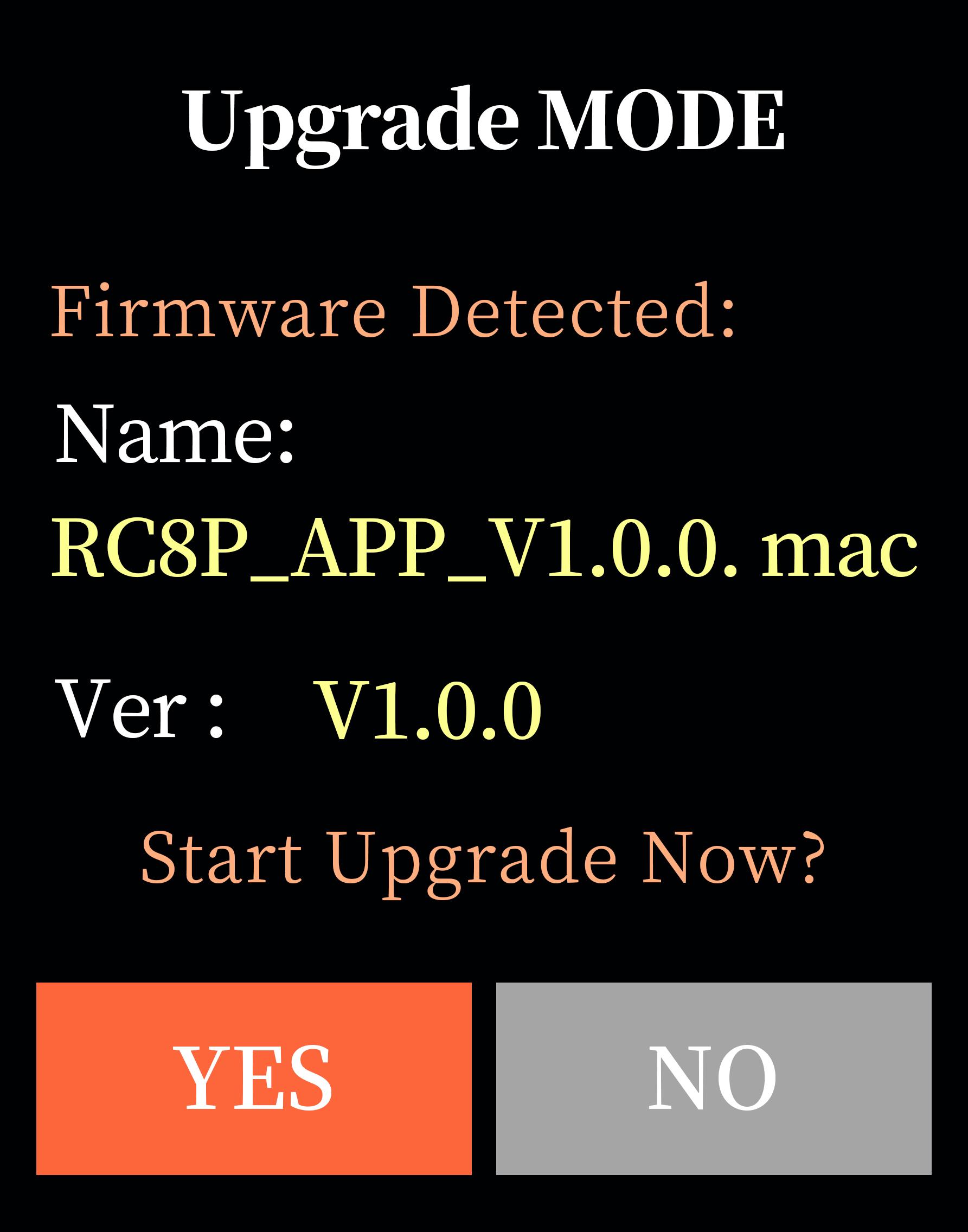
The following Upgrade MODE interface will appear on the screen, indicating that it has entered upgrade mode. Select "YES" and press the scroll key to confirm;
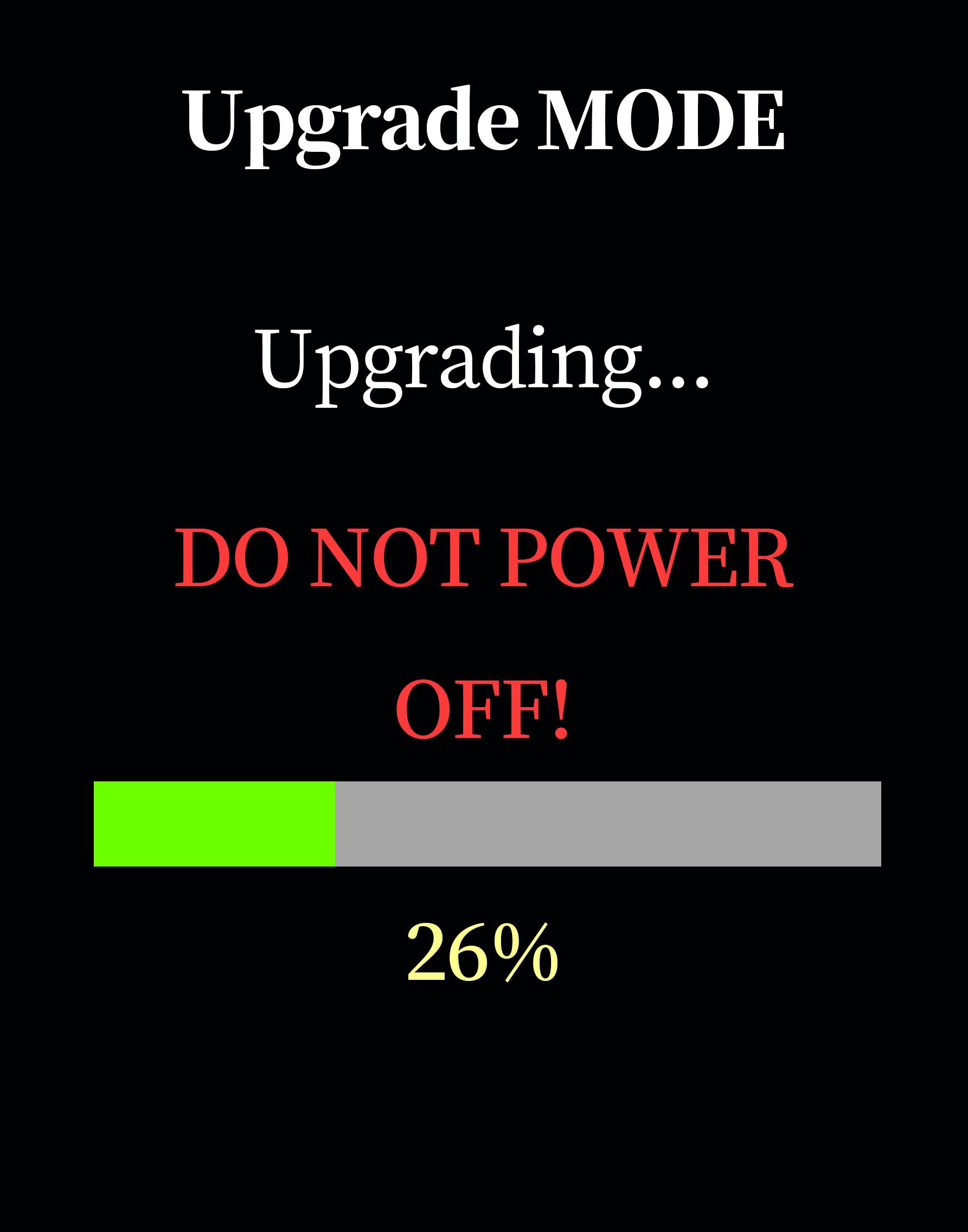
The transmitter starts to upgrade the firmware, and the percentage of the interface indicates the progress of the firmware upgrade;
Note: Do not disconnect the USB connection or turn off RC8P during the upgrade process.
7.Firmware upgrade successful
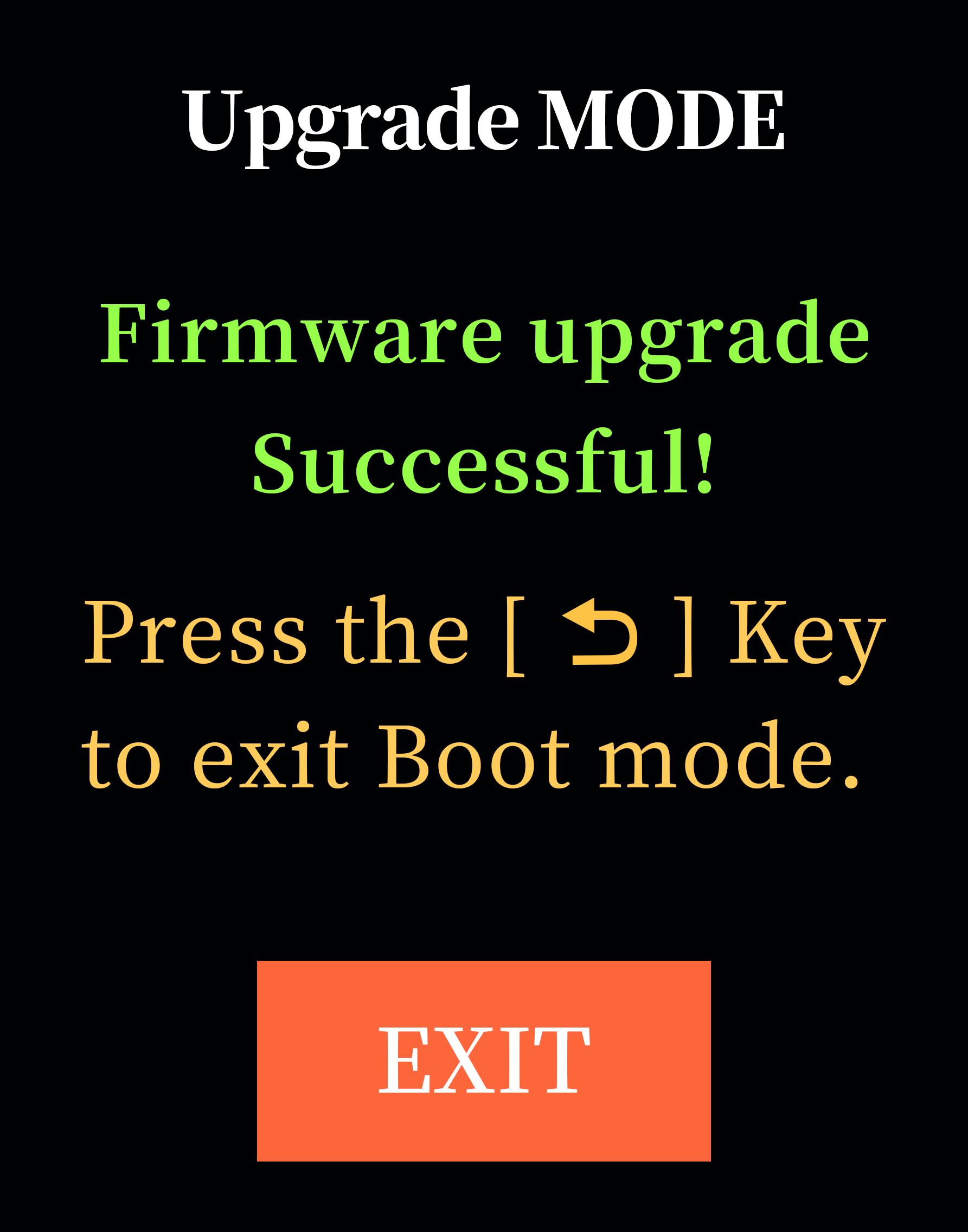
When“Firmware upgrade successful!”appears on the screen, the upgrade is successful;
8.Exit upgrade mode
Short press the Return button to exit upgrade mode. RC8P will automatically power off;
Long-press the Power button to turn it on, and the transmitter is ready for normal use.
Chapter 4 Customized Switch Audio Production
RC8P supports customized switch audio. Users can use text-to-speech software to create custom voice files, and then copy the voice files into the transmitter to use their own voice. The production method mainly includes the following three steps:
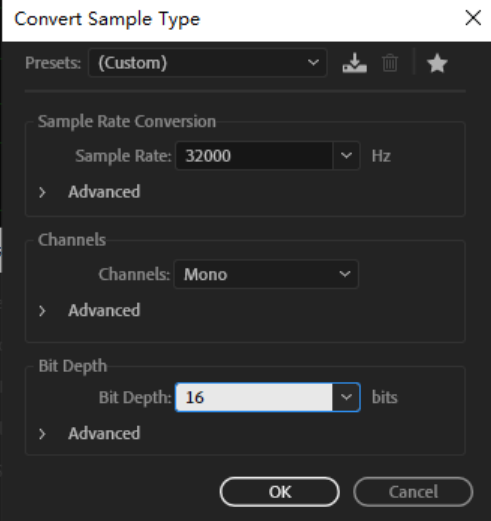
1.After recording the voice file, modify the format of the voice file to ensure that the format of the voice file meets the following four conditions:
a.WAV format
b.Sampling rate 16KHZ or 32KHZ
c.Mono
d.Bit depth 16 bits
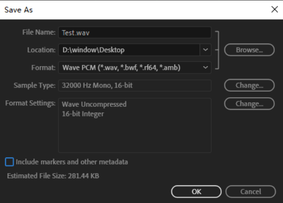
The following pictures show how to convert the format of an audio file to make it meet the above 4 conditions. Take Adobe Audition voice software as an example: Import the voice file whose format needs to be modified into Adobe Audition software, and then click File - Save As.
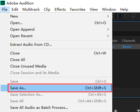
Modify the voice file format to ensure that the format conforms to WAV format, Sample rate 16KHZ or 32KHZ, monophonic, and 16 bits depth. After selecting the save location, click OK, and a qualified voice file will be generated.
Note: Don't tick "Include markers and other metadata".
2. Copy the voice file into RC8P.
(1)Enter USB mode
With RC8P transmitter powered off, connect RC8P to the computer using the Type-C cable that comes with it;
Press and hold the Return button while simultaneously pressing and holding the Power button to turn on RC8P;
The following BOOT MODE interface will appear on the screen of the transmitter. Select "USB" and press the scroll key to confirm;
The following USB MODE interface will appear on the screen, indicating that it has entered USB mode, and the computer will recognize the disk of RC8P;
(2)Copy the audio file
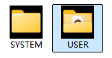
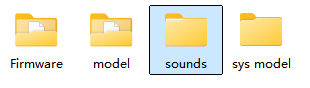
The computer will display the removable disk of RC8P. Open the disk. Copy the audio filesinto RC8P-sounds-USER folder.
Note: The audio copied into the transmitter needs to be named according to the user's needs, so that the user can select the corresponding voice file on the transmitter.
3. After the copy is completed, exit the USB mode. Power on RC8P, and then you can select the audio file in SW AUDIO menu.
Tutorial on how to make customized switch voice on RC8P:
https://www.youtube.com/watch?v=j7Em6ZpOQA4
Technical Support Here


Contact RadioLink RL RC8P User Manual RC8P FAQ RC8P Tutorials
via acebook Messenger
If the above communication cannot solve your problem, you can also send emails to our technical support: after_service@radiolink.com.cnThis content is subject to change. Please download the latest version from https://www.radiolink.com/rc8p_user_manual
Thank you again for choosing RadioLink product.