
Function One:Obstacle Avoidance
Firmware support
The firmware of the obstacle avoidance function needs to be downloaded from the link below, and then uploaded to the flight controller on Mission Planner. Other versions of firmware cannot be used! ! ! (The following firmware is modified from Firmware Copter V3.5.7. After installing the firmware, the previous functions and parameters will remain unchanged, and there is no need to re-calibrate)
SUI04 Firmware for Obstacle Avoidance Function:
https://www.radiolink.com/sui04_firmware
How to connect
2.1 With PIXHAWK
2.1.1 Individually with PIXHAWK
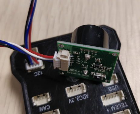
Connecting the module (eg. SUI 04) and the I2C port of PIXHAWK with a 4 pin to 4 pin wire
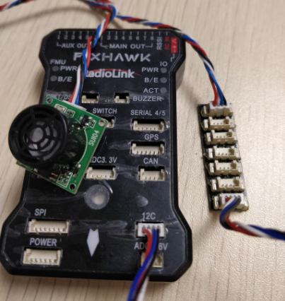
2.1.2 Connecting with PIXHAWK by I2C wiring board
2 wires of 4 pin to 4 pin are needed: one for connecting I2C port of PIXHAWK and I2C wiring board; one for connecting I2C wiring board and SUI04
2.2 With MINIPIX
WARNING: NO memory card inside.
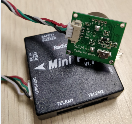
2.2.1 Individually with MINIPIX
A 4 pin to 6 pin wire is needed: the 4 pin end to SUI04 and the 6 pin end to the GPS port of MINIPIX
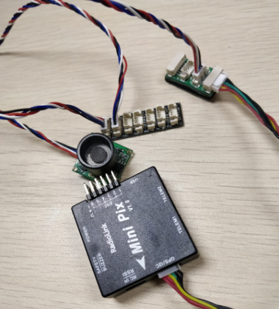
2.2.2 Connecting with MINIPIX by I2C wiring board
Take a 6 pin to 6 pin wire with one end to the GPS port of MINIPIX and one end to the I2C expansion board.
Take a 4 pin to 4 pin wire with one end to the I2C expansion board and one end to the I2C wiring board.
Take another 4 pin to 4 pin wire with one end to the I2C wiring board and one end to the SUI04
Parameters Setup
3.1 Module type setup
PIXHAWK support four kinds of obstacle avoidance modules. SUI04 can be chosen by setting the value of PRX_TYPE in Mission Planner(MP).
Setting steps:
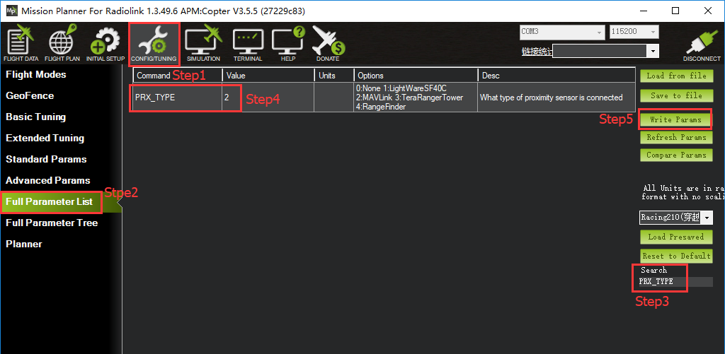
Choose CONFIG/TUNING on the top of the interface.
click “Full Parameter List”on the left.
Input“PRX_TYPE”(obstacle avoidance module type) in search column at the lower right corner and press “Enter”.
As the searched proximity sensor type shown in the MP, change the proximity sensor type value to 4 ( that is , the chosen module type is Range Finder,which is SUI04 ).
Click “Write Params”on the right to save the parameters when the setting is complete.
3.2 Setup the avoidance distance and the avoidance enable/disable
The avoidance distance of ultrasonic sensor SUI04 can bechanged by setting the value of AVOID_MARGIN.
AVOID_MARGIN: the max avoidance distance at LoiterMode, the unit is meter
The avoidance enable/disable of ultrasonic sensor SUI04 can be set by changing the value of AVOID_ENABLE.
AVOID_ENABLE: the value of AVOID_ENABLE0(options is None) means the avoidance function is off and the value 2(options is Use Proximity Sensor) means the avoidance function is on.
Parameters Setting Steps on MP:
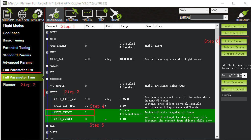
Choose CONFIG/TUNING on the top of the interface
Click “Full Parameter Tree”
Click the “AVOID”, the parameters of “AVOID_ENABLE” and “AVOID_MARGIN”are shown
Set the value of the AVOID_ENABLE 2(use proximity sensor) means make avoidance sensor enable
Set the value of AVOID_MARGIN 3(3 meters, the effective value is from 1 to 10) means vehicle will attempt to stay at least in 1 to 10 meters from objects while in GPS modes.
Click “Write Params”on the right to save the parameters when the setting is complete.
3.3 How to Enable/Disable the avoidance function by transmitter(Optional)
This setup depends on users’habit and is optional.
The avoidance function of flight controller is always automatically enabled a LoiterModeby default anddisabled ifchange to Stabilize Mode.
If users prefer enabling/disabling the avoidance function by transmitter, setup in the Mission Planner as
Below steps is necessary.
Flight Controller Setting steps (CH7_OPT Parameters):
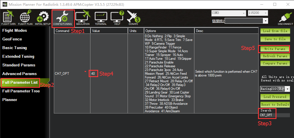
Choose CONFIG/TUNING on the top of the interface
click “Full Parameter List”on the left
Input“CH7_OPT”(choose the CH7 to make the avoidance function enable or disable) in search column at the lower right corner and press “Enter”
As the searched CH7_OPT shown in the MP, change the value to 40 (Object Avoidance).It means switchon/off CH7 enable/disable the avoidance function.
Click “Write Params”on the right to save the parameters when the setting is complete.
Transmitter setting steps
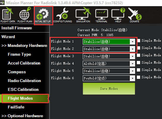
Choose a 2-position switch(the SWA of AT9S for example) to control CH7
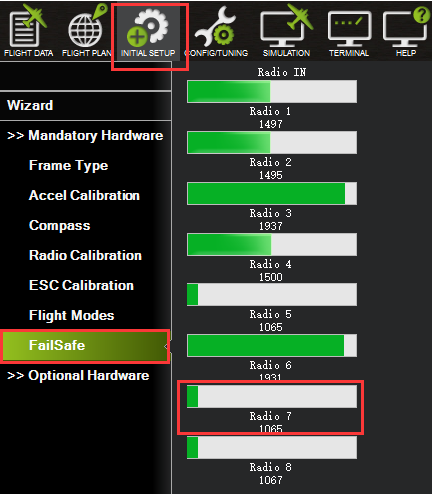
Choose INITIAL SETUP on the top of the interface
Click “FailSafe”in the pull-down menu of “ Madatory Harware” on the left and the PWM value interface of CH7 is shown
Toggle the switch. If the PWM value of CH7 is more than 1800, it means the avoidance function is enabled when the switch is at the bottom position. If the PWM value of CH7 is less than 1800, it means the avoidance function is disabled when the switch is at the top position.
4.1 Button Functions of SUIO4
Flight controller PIX can simultaneously support 6 modules (eg. SUI04) including front/back/left/right/upward/downward. So the direction of each module should be set. Every press on the button, the module direction changes once accordingly clockwise and the module LED flashes. Different flash frequencies means different directions. Once-Front, Twice-Right, 3 Times-Back, 4 Times-Left, 5 Times-Downward, 6 Times- Upwards.
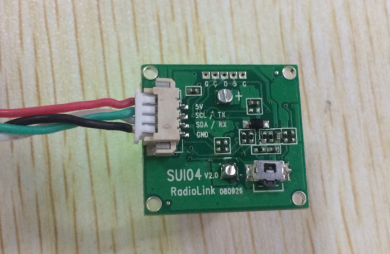
(Press this button to change the direction of obstacle avoidance, it will rotate 90 degree clockwise when press the button once.)
NOTICE: Every direction changed, the flight controller and the module need to be restarted.
5.1Data Check
As the data of the latest official MP is not well shown, it’s suggested to download the Mission Planner specially for MINIPIX to check data.
http://www.radiolink.com.cn/firmware/MissionPlanner/MissionPlanner-1.3.49.6.exe
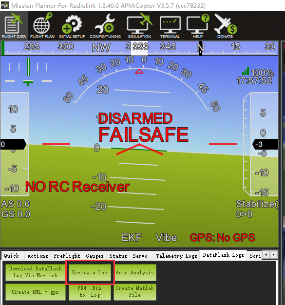
After the above setups are complete, the SUI04 data can be checked on MP. Disconnect the PIXHAWK and restart the Mission Planner. When the MP is connecting, a new interface (as shown below) will come out automatically and the working condition of SUI04 can be checked . If it doesn’t come out, please click the icon at the task bar on the desktop.
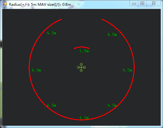
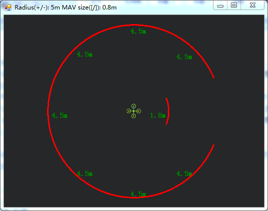
( Current direction: Forward ) ( Current direction: Right)
Flight Modes
Flight modes need to setup after the parameters of PIXHAWK have been set and the Ultrasonic Sensor SUI04 works , the basic flight modes include 1: Stabilize, 2: Loiter.
Working Condition
WARNING:Reconnect the PIXHAWK and restart the MP after following all the above steps to ensure the successful parameters setup for failsafe.
After verifying all the parameters setup, it’s strongly suggested to find a large place with walls or other obstacles to have a test when ready for the first flight.
Flight testing steps:
Power on the drone and wait till the blue LED of PIXHAWK blinks,meaning the initialization of PIXHAWK is complete.
Press the safety switch about 1 to 2 seconds till the red LED of PIXHAWK is on when the blue LED of PIXHAWK is blinking.
Unlock the drone and the motors will begin to move if armed successfully. Push the throttle stick slowly, change the flight mode to Loiter when the drone takes off.
Toggle the CH7-SWA(or any other 2 position switch, it depends on which you setup at the very beginning) to turn on the avoidance function.
Push the throttle and aileron sticks to make the drone close to the wall/obstacle, the drone will control the racing speed and stopped at the 3 meters far from the wall/obstacle automatically. If the flight speed is too high and the distance to the wall/obstacle is less than 3meter because of the inertia, the drone will stay at 3 meters away from the wall or obstacle automatically.
Notice: To unlock a drone, put the throttle stick to the bottom right corner if the transmitter is Mode2. Or put the throttle stick to the bottom left corner and the aileron stick to the bottom right if your transmitter is Mode1
Notices:
No memory card allowed when connecting MINIPIX.
Avoidance function is automatically enabled when at Alt-Hold Mode. If needs to be disabled, please follow the above steps and change the value of AVOID_DIST_MAX to 0 in Param Setup in MP.
Never enable the avoidance function of SUI04 at Alt-Hold Mode but Loiter Mold.
(At Alt-hold mode, when the drone encounter obstacles, its slant angle will combine pitch with roll then response.It may be too late to stop if the drone is at full speed. But at Loiter Mode, the drone will stop immediately when encounter an obstacle no matter how big both the pitch and roll are. So, it’s suggested use the horizontal obstacle avoidance function at the Loiter Mode.)
When obstacles detected, the LED of SUI04 is always on; When no obstacle detected, the LED of SUI04 keeps flashing.
If connection is successfully done, the LED of SUI04 will flash 4 to 6 times and be off when power on.Then always on after the initialization.
Be sure to avoid the interference from propellers and frame to signals when connecting the flight controller.
As SUI04 is a transceiver, there is a blind area of 40cm, including the area less than 40cm.
Only the distance of horizontal directions can be checked on the data check interface. When there’s no distance shown, the current direction of SUI04 may be upward, which can be checked on DataFlash Logs.
Errors Report on Mission Planner
MP note: Bad LiDAR Health, as shown below
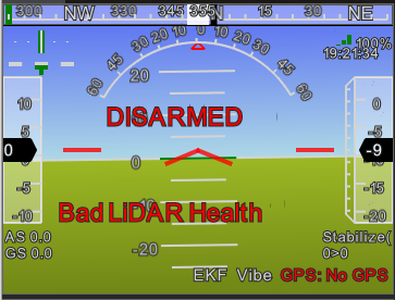
The ultrasonic shown in the above pic is under unusual working condition.The possible reasons are:
PRX_TYPE value is set wrong
PRX_TYPE value is set 4, but SUI04 is not connected. If SUI04 need to be turned off, PRX_TYPE value should be set 0.
SUI04 connect incorrectly
MP note: PreArm: Proximity X deg,0.40m, as shown below
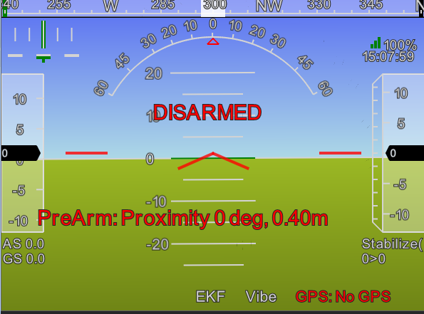
The above screenshot shows SUI04 detects the distance less then 60cm and is locked by the flight controller. To armed SUI04, the distance between the drone and obstacles should be more than 60cm.
Function Two:Collision Avoidance Upward
The collision avoidance upward function is same as the obstacle avoidance function, the direction of SUI04 upward can be setup by pressing the same button.
Press the button 6 times and the LED flashes 6 times, and the direction of SUI04 is set upward.
The corresponding distance of collision avoidance can be set by the value of AVOID_MARGIN as the previous steps instructed.
As only the horizontal distances are available on the data check interface, upward data can be checked on DataFlash Logs.
DataFlash Logs Download
Connect the flight controller with MP and follow the below steps to download DataFlash Logs
Clickthe logs and download
Log check
Open the log files
Click the log review and open the log
Follow the Step 1 and Step 2 shown in below pic:
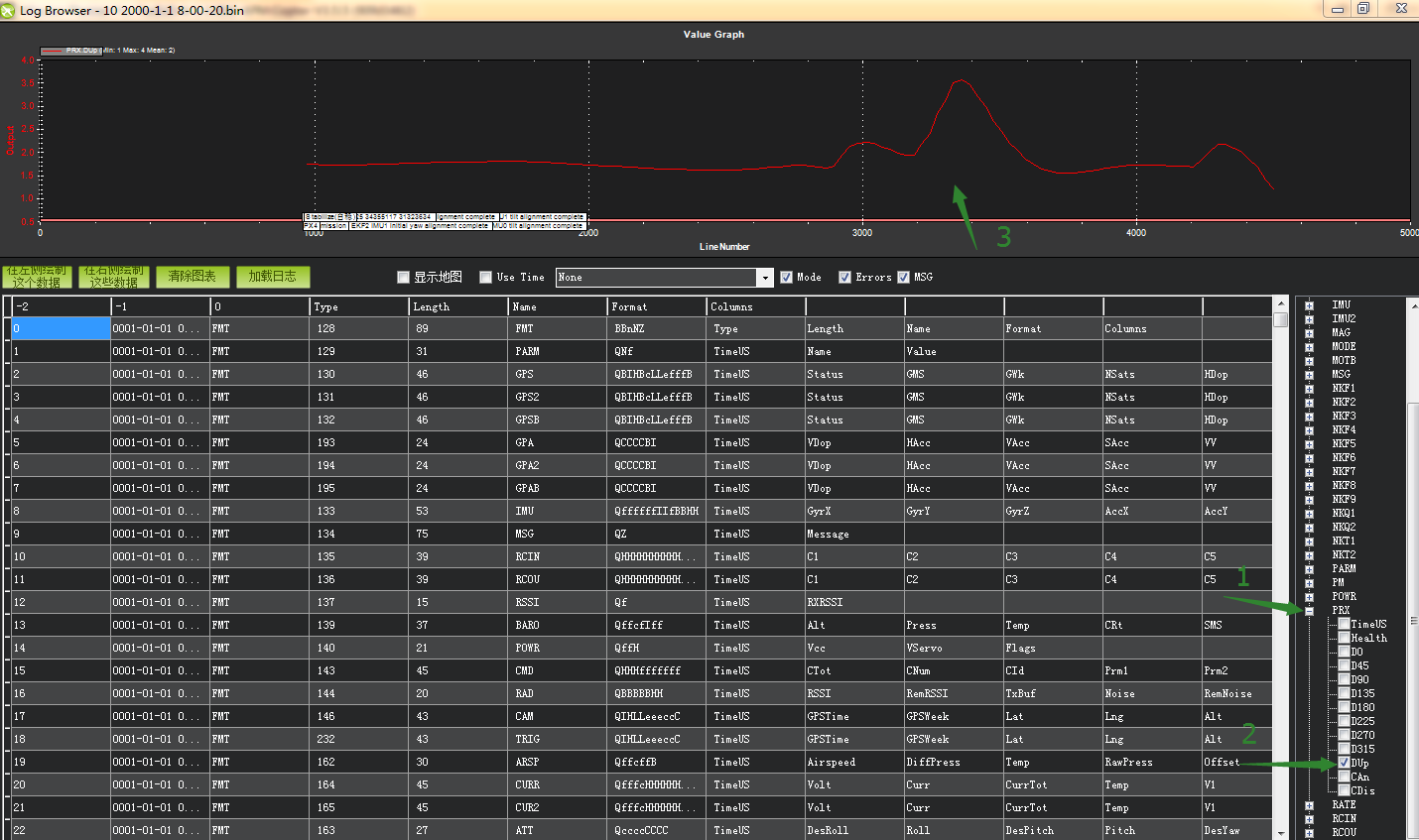
(The data that arrow points to means the distance that SUI04 detects.)
Function Three:Alt-Hold Function Downward
How to Connect
The Alt-Hold downward function is same as the obstacle avoidance function, the direction of SUI04 downward can be setup by pressing the same button.
Press the button 5 times and the LED flashes 5 times, and the direction of SUI04 is set downward.
1.1 With PIXHAWK
1.1.1 Individually with PIXHAWK
Connect SUI 04 and the I2C port of PIXHAWK with a 4 pin to 4 pin wire
1.1.2 Connecting with PIXHAWK by I2C wiring board
2 wires of 4 pin to 4 pin are needed: one for connecting I2C port of PIXHAWK and I2C wiring board; one for connecting I2C wiring board and SUI04
1.2 With MINIPIX
WARNING: NO memory card inside.
1.2.1 Individually with MINIPIX
A 4 pin to 6 pin wire is needed: the 4 pin end to the module (eg. SUI04) and the 6 pin end to the GPS port of MINIPIX
1.2.2 Connecting with MINIPIX by I2C wiring board
Take a 6 pin to 6 pin wire with one end to the GPS port of MINIPIX and one end to the I2C expansion board.
Take a 4 pin to 4 pin wire with one end to the I2C expansion board and one end to the I2C wiring board.
Take another 4 pin to 4 pin wire with one end to the I2C wiring board and one end to the SUI04
The alt-hold function is same as the obstacle avoidance function, the direction of SUI04 downward can be setup by pressing the same button.
Press the button 5 times and the LED flashes 5 times, and the direction of SUI04 is set upward.
Parameters Setup
2.1 Module type setup:
Click “INITIAL SETUP”on the top
Click “Optional Hardware”on the left
Click “Range Finder”and the RangeFinder interface is on the right
Click the pull-down menu and choose “MaxbotixI2C” or “LightWareI2C”
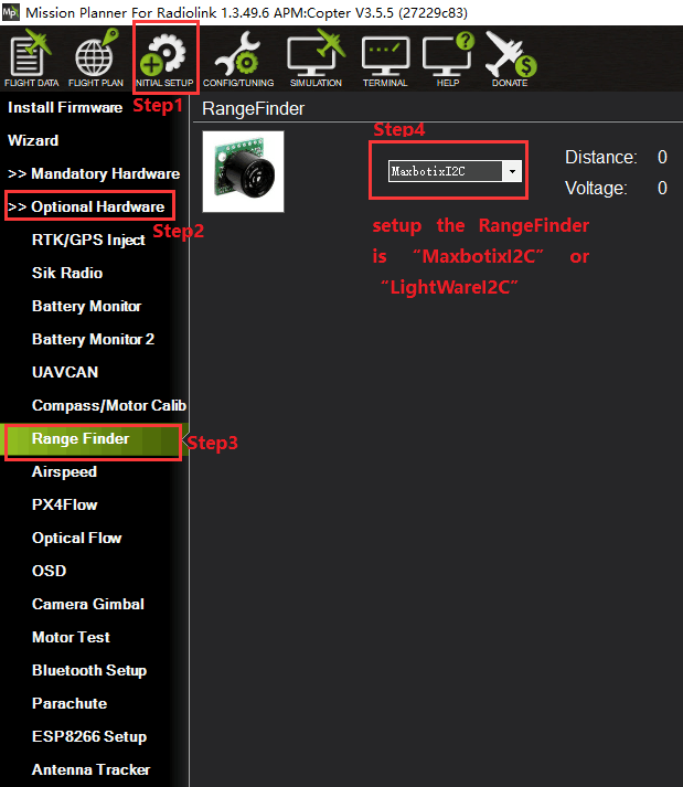
After the Range Finder setup,restart the flight controller and back to this Range Finder setup menu, the shown detection distance details means the parameters setup is complete.
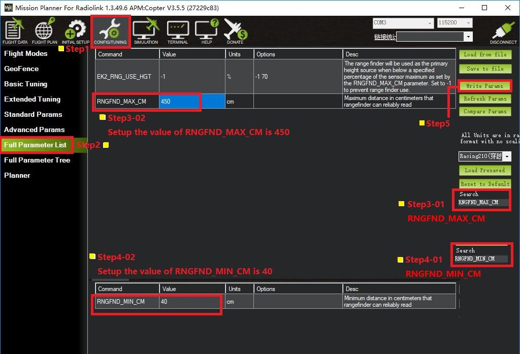
2.2 Setting steps:
Choose CONFIG/TUNING on the top of the interface
Click “Full Parameter List”on the left
Input“RNGFND_MAX_CM”and “RNGFND_MIN_CM”in search column at the lower right corner and press “Enter”
As the searched the two items shown in the MP, change RNGFND_MAX_CM value to 450cm and RNGFND_MIN_CM value to 43 cm
Click “Write Params”on the right to save the parameters when the setting is complete.
RNGFND_MAX_CM is the detectable max distance of flight controller at Alt-Hold Mode
RNGFND_MIN_CM is the detectable min distance of flight controller at Alt-Hold Mode
2.3 How to Enable/Disable the Alt-Hold function by transmitter(Optional)
This setup depends on users’habit and is optional.
The Alt-Hold function of SUI04 is always automatically enabled at Alt-Hold Mode and Post-Hold Mode by default anddisabled ifchange to Stabilize Mode.
If users preferenabling/disabling the Alt-Hold function by transmitter, setup in the Mission Planner is necessary.
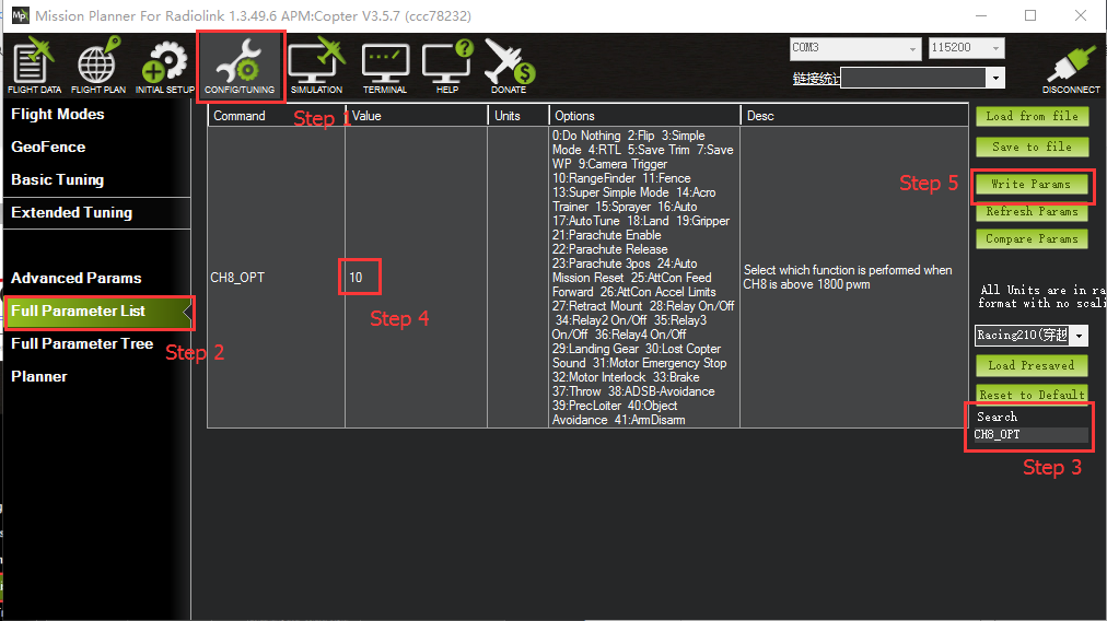
Flight Controller Setting steps (CH8_OPT Parameters):
Choose CONFIG/TUNING on the top of the interface
Click “Full Parameter List”on the left
Input“CH8_OPT”(choose the CH8to make the Alt-Hold function enable or disable) in search column at the lower right corner and press “Enter”
As the searched CH8_OPT shown in the MP, change the value to10 (Object Alt-Hold).It means switchon/off CH7 enable/disable the avoidance function.
Click “Write Params”on the right to save the parameters when the setting is complete.
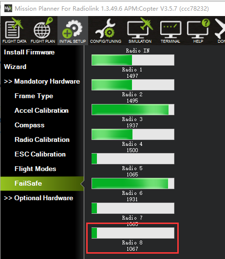
Transmitter settings
Choose a 2-position switch to control CH8
Choose INITIAL SETUP on the top of the interface of MP
Click “FailSafe”in the pull-down menu of “ Madatory Harware” on the left and the interface of CH8 PWM value is shown
Toggle the switch. If the PWM value of CH8 is more than 1800, it means the Alt-Hold function is enabled when the switch is at the bottom position. If the PWM value of CH8 is less than 1800, it means the Alt-Hold function is disabled when the switch is at the top position.
Specifications
Size: 20*22*19mm
Weight: 8g (with wires)
Input voltage: 4.5~5.5V(do not support HV)
Current: 18mA@5V
Power: 90mA
Operating temperature: -20°C~80°C
Detection distance: 40cm~450cm
Detecting precision: 0.1cm
Acoustic emission frequency: 40±1.0KHz
Beam angle: 60°(transmitting receiving hybrid)
Fade area: 0 (it will show 40cm)
Output protocol: I2C
Duty Cycle: 30ms
Set CrossFlight and SUI04
The SUI04 module can realize Alt-hold, obstacle avoidance in four directions (front, rear, left and right), and upward collision avoidance. Here is how to set CrossFlight to work with SUI04.
Chapter 1. Connect SUI04 to CrossFlight
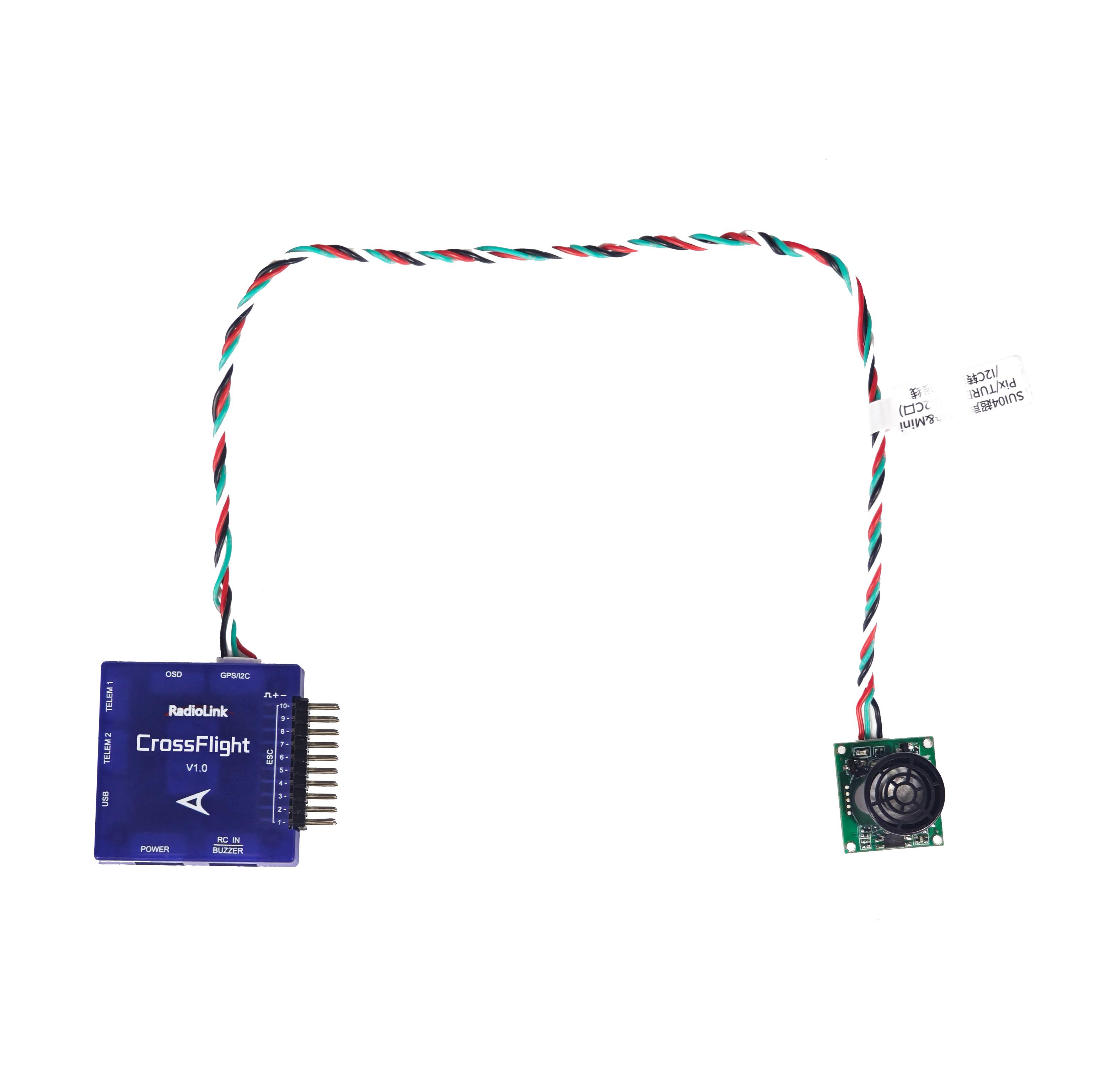
1.1 Connect SUI 04 to CrossFlight GPS port directly
SUI04 comes with a cable to connect CrossFlight/Mini Pix flight
controller(4 Pin to 6 Pin). The 4 Pin end is connected to SUI04, and the 6 Pin end is connected to the GPS port of CrossFlight, as shown below:
1.2 Connect SUI 04 to CrossFlight by I2C transfer board
CrossFlight comes with a I2C transfer board and its connect cable(6 Pin to 6 Pin). Connect one end to the GPS port of CrossFlight, and the other end to the I2C transfer board. Then use the 12C/PIXHAWK connect cable that comes with SUI04 (4 Pin to 4 Pin) to connect one end to the I2C transfer board, and the other end to SUI04, as shown below:
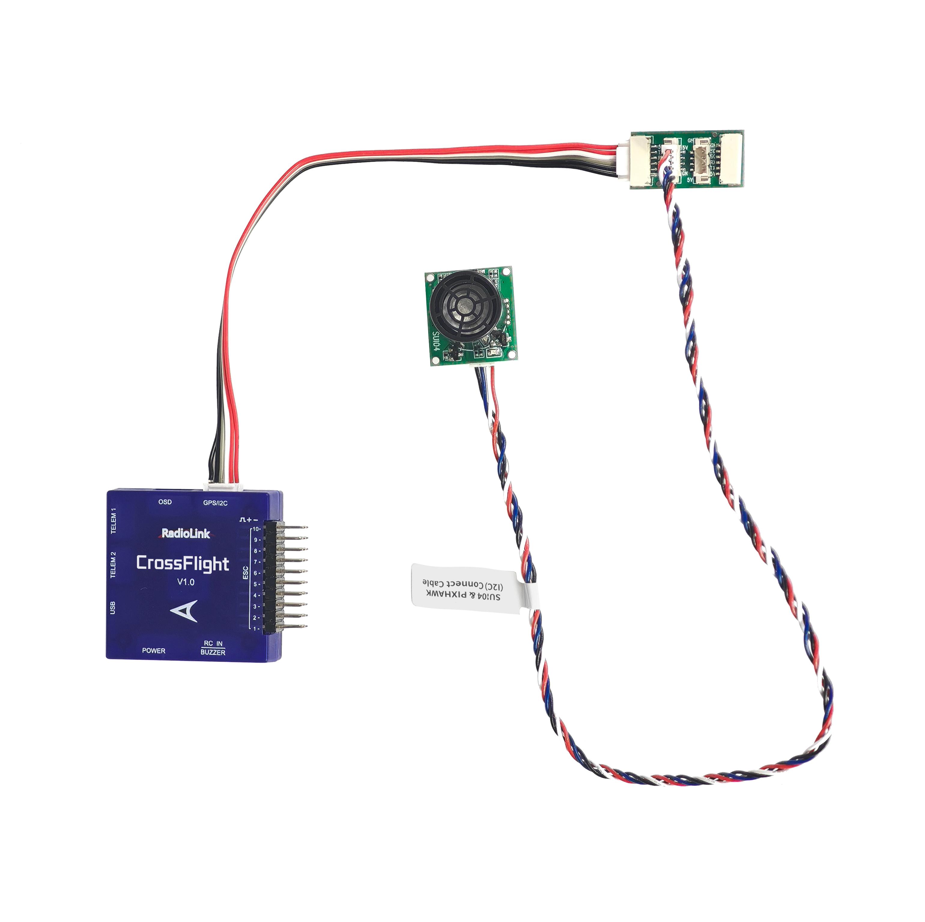
Note: The I2C port of CrossFlight cannot be connected to more than 6 devices at the same time, otherwise data loss may occur.
Chapter 2. Alt-Hold Function
2.1 Button Functions of SUI04
For Alt-hold function, the direction of SUI04 downward can be setup by pressing the same button. Each time you press the button, the module direction changes once. After pressing once, you need to wait for the module light to flash. When finished, press it a second time until the light of SUI04 flashes 5 times, which means the current direction of the module is downward.
2.2 Parameter Setup
1. Connect the flight controller to Mission Planner. Enter CONFIG--Full Parameter List. Search RNGFND1_ and change the value of RNGFND1_TYPE to 2. Click Write Params. Then power off the flight controller and restart it.
2. After reconnecting to Mission Planner, SUI04 can be recognized. As shown below:
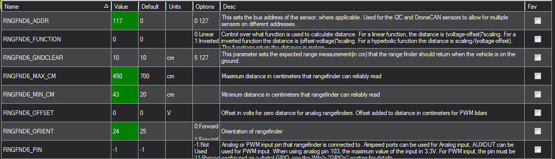
Change the value of RNGFND1_MAX_CM to 450, RNGFND1_MIN_CM to 43 (cm), and RNGFND1_ORIENT to 25. As shown below:
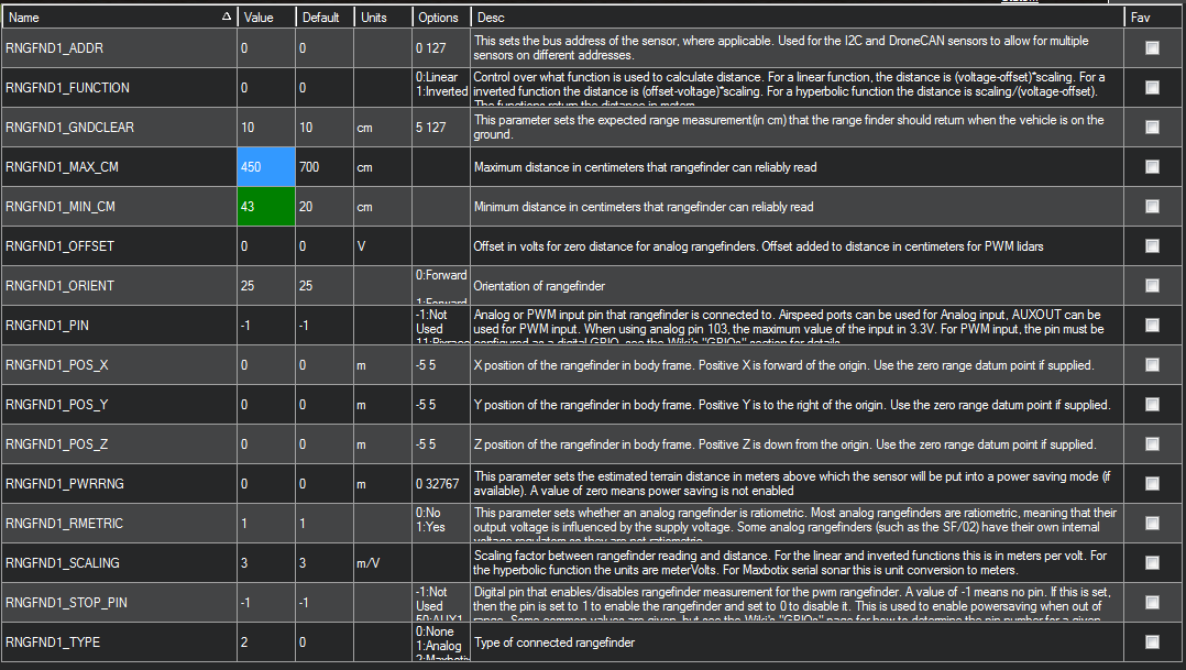
RNGFND1_MAX_CM is the maximum distance in centimeters that rangefinder can reliably read.
RNGFND1_MIN_CM is the minimum distance in centimeters that rangefinder can reliably read.When the distance sent by SUI04 exceeds 43~450cm, the flight control will not recognize the distance of SUI04, so it will achieve the alt-hold by the barometer.
2.3 Data View
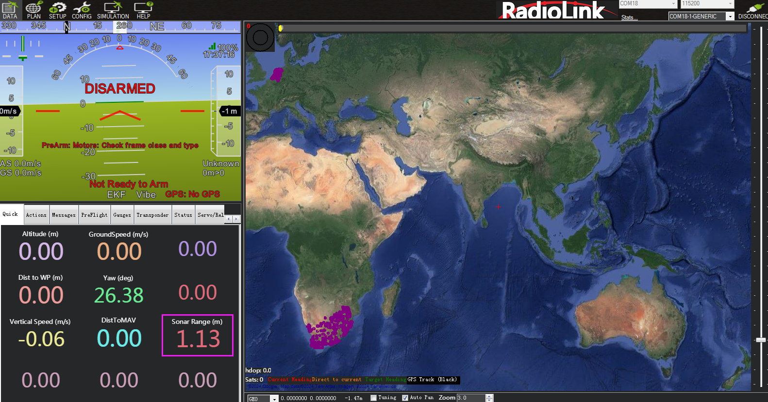
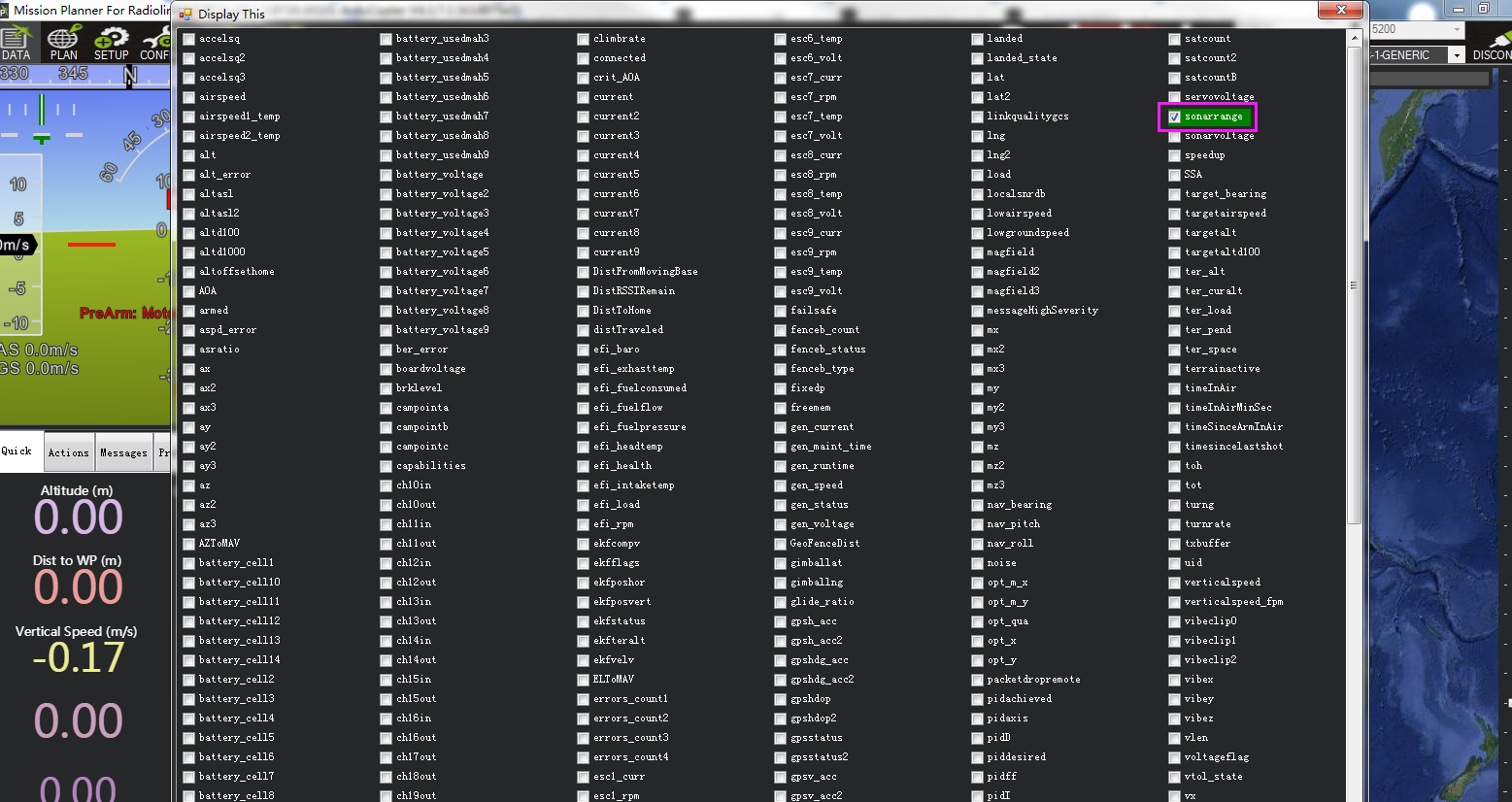
1. View ultrasonic data in the quick interface.
Connect the flight controller to Mission Planner. Double-click in the quick interface, and a large list will appear. Select sonarrange in the list, and the ultrasonic height data will be displayed.
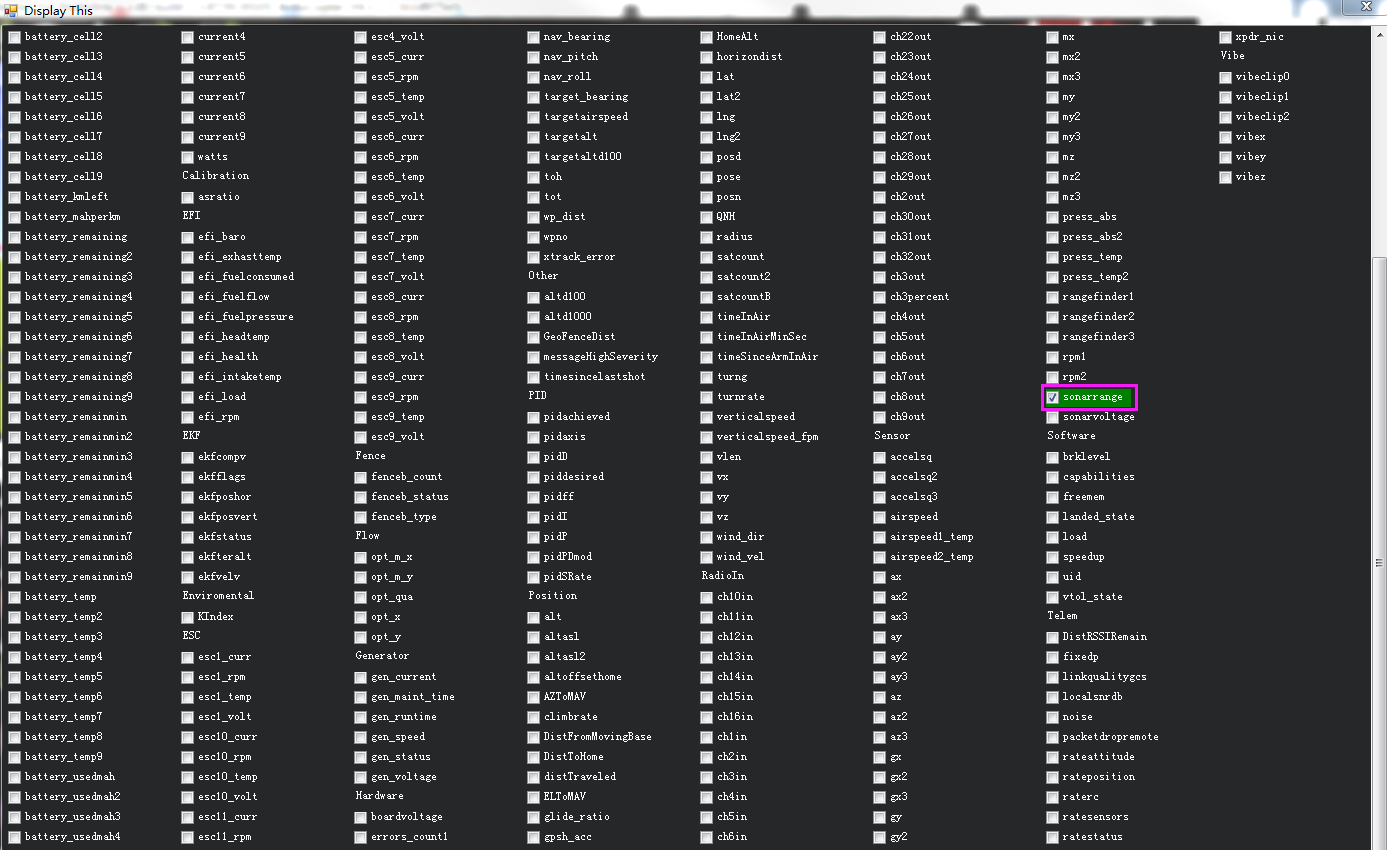
View ultrasonic data in the Tuning interface.
Check the Tuning option in Mission Planner. Double-click the dynamic table, and select sonarrange in the list to display the dynamic waveform of ultrasonic data. As shown below:

Chapter 3. Obstacle Avoidance
3.1 Button Setup
The SUI04 module can realize obstacle avoidance in four directions (front, rear, left and right). The directions can be changed by pressing the button on SUI04. The default direction of the module is forward. Each time the button is pressed, the direction of the module changes clockwise, and the module LED flashes. Different flash frequencies means different directions: Once-Front, Twice-Right, 3 Times-Back, 4 Times-Left. After the direction is set, the module needs to be powered off and restarted.
3.2 Parameter Setup
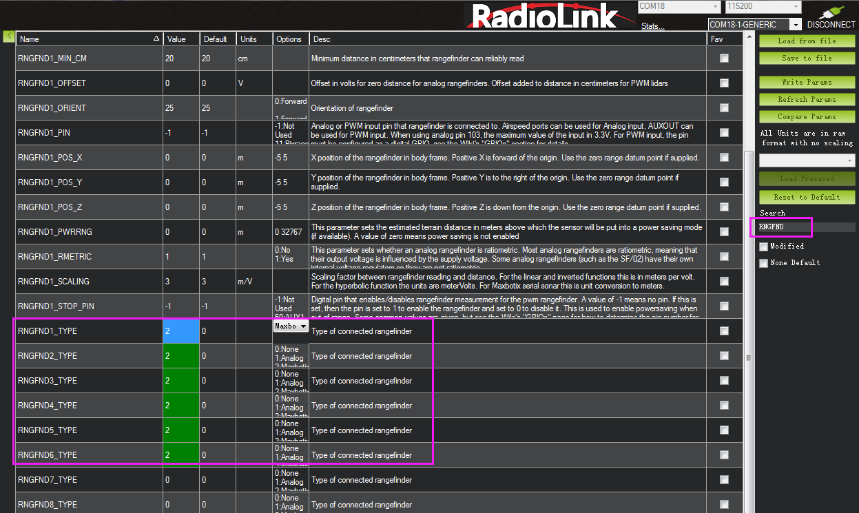
1. Connect SUI04 to the flight controller. Search PRX1_TYPE in Full Parameter List and change the value to 4. Then search RNGFND in Full Parameter List and change the value of RNGFNDx_TYPE to 2 (x represents the ultrasonic serial number). Finally restart the flight controller. As shown below:

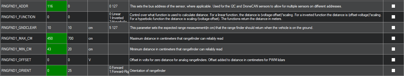
2. Search RNGFND1 in Full Parameter List. Modify RNGFND1_ADDR to 116, RNGFND1_MAX_CM to 450, RNGFND1_MIN_CM to 43, and RNGFND1_ORIENT to 0. (0 indicates that the ultrasonic direction is forward) As shown below:
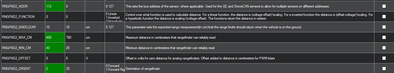
Search RNGFND2 in Full Parameter List. Modify RNGFND2_ADDR to 113, RNGFND2_MAX_CM to 450, RNGFND2_MIN_CM to 43, and RNGFND2_ORIENT to 2 (2 indicates that the ultrasonic direction is to the right) As shown below:
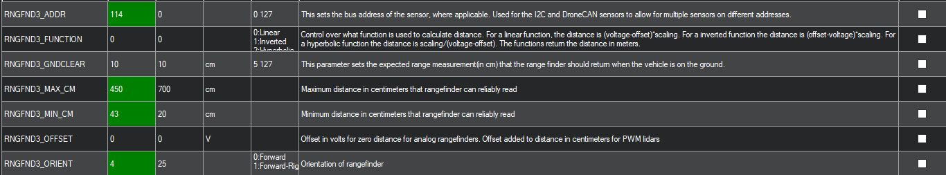
Search RNGFND3 in Full Parameter List. Modify RNGFND3_ADDR to 114, RNGFND3_MAX_CM to 450, RNGFND3_MIN_CM to 43, and RNGFND3_ORIENT to 4 (4 indicates that the ultrasonic direction is backward) As shown below:
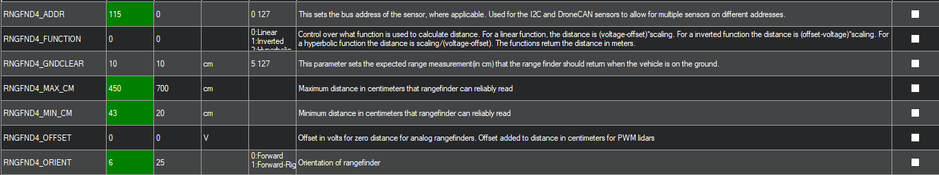
Search RNGFND4 in Full Parameter List. Modify RNGFND4_ADDR to 115, RNGFND4_MAX_CM to 450, RNGFND4_MIN_CM to 43, and RNGFND4_ORIENT to 6 (6 indicates that the ultrasonic direction is to the left) As shown below:
Click Write Params. Then power off the flight controller and restart it. After reconnecting to Mission Planner, SUI04 can be recognized.
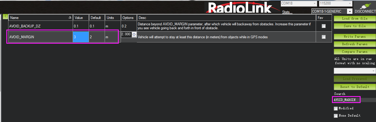
3.3 Set the Avoidance Distance and Avoidance Enable/disable1. The obstacle avoidance distance of SUI04 can be set by changing the value of AVOID_MARGIN.
AVOID_MARGIN: Vehicle will attempt to stay at least this distance (in meters) from objects while in GPS mode.
2. Parameter Settings
Search AVOID_MARGIN in Full Parameter List, and modify it to 3 (That is, 3 meters. The valid value is 1~10). Then click Write Params.
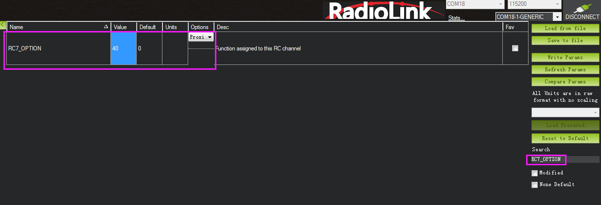
Set RC7_OPTION
Search RC7_OPTION in Full Parameter List, and modify it to 40. Then click Write Params. As shown below:
Transmitter Setup
This setup is optional.
The avoidance function of flight controller is always automatically enabled in Loiter Mode by default and disabled in Stabilize Mode. If users prefer enabling/disabling the avoidance function by transmitter, setup the transmitter by following the below steps:
Choose a 2-position switch to control CH7.
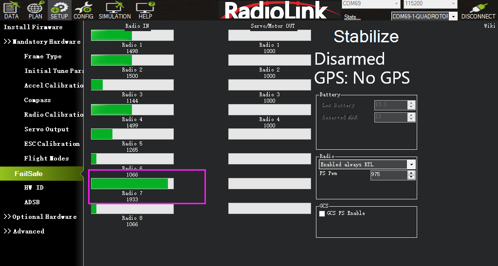
Connect Mission Planner. Enter SETUP-- Mandatory Hardware--FailSafe. The PWM value of CH7 is shown.
Toggle the switch of CH7. If the PWM value of CH7 is more than 1800, it means the avoidance function is enabled when the switch is at the position. If the PWM value of CH7 is less than 1800, it means the avoidance function is disabled when the switch is at the the position.
3.4 Data Display
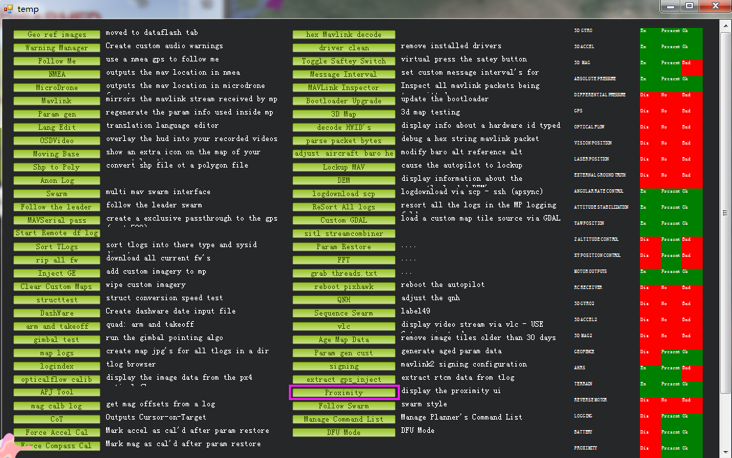
Connect the flight controller to Mission Planner. Press CTRL+F on the keyboard, and click Proximity in the pop-up window. As shown below:
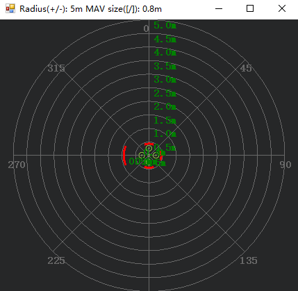
Ultrasound data can be displayed in a pop-up window, as shown below:
Chapter 4. Collision Avoidance Upward
4.1 Button Setup
The collision avoidance upward function is the same as the obstacle avoidance function, the direction of SUI04 upward can be setup by pressing the same button. Press the button 6 times and the LED flashes 6 times, and the direction of SUI04 is set upward. The corresponding collision avoidance distance can be set by the value of AVOID_MARGIN as the previous steps instructed.
4.2 Parameter Setup
1. Connect SUI04 to the flight controller. Search PRX1_TYPE in Full Parameter List and change the value to 4. Then search RNGFND in Full Parameter List and change the value of RNGFNDx_TYPE to 2 (x represents the ultrasonic serial number). Finally restart the flight controller. As shown below:
Search RNGFND in Full Parameter List. Modify RNGFNDx_ADDR (x represents the ultrasonic serial number) to 117, RNGFNDx_MAX_CM to 450, RNGFNDx_MIN_CM to 43, and RNGFNDx_ORIENT to 24. (24 indicates that the ultrasonic direction is forward) As shown below:
4.3 Data Display
As only the horizontal distances are available on the data check interface, upward data can only be checked on DataFlash Logs. The steps are as follows:
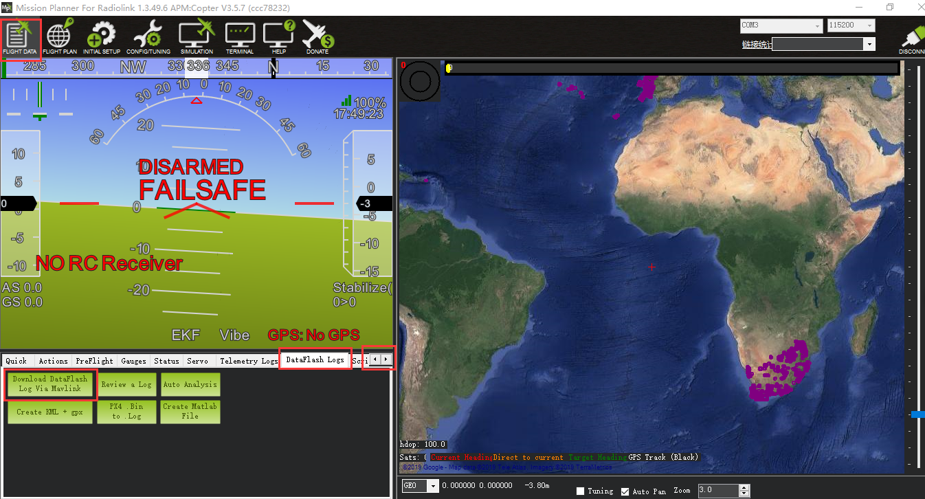
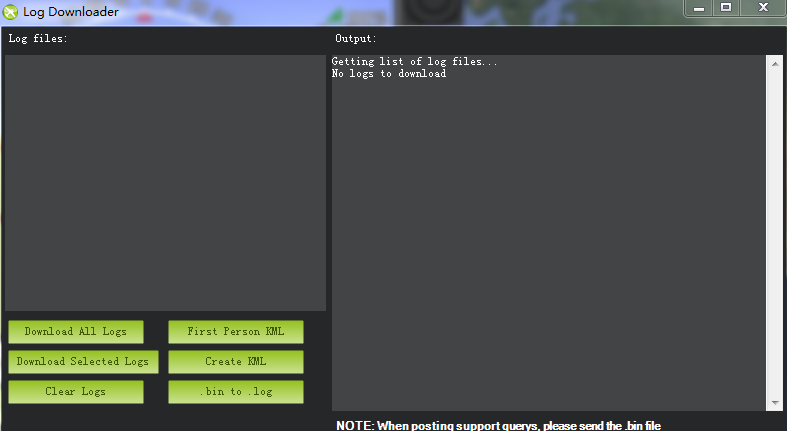
DataFlash Logs Download
Connect the flight controller to Mission Planner and follow the below steps to download DataFlash Logs.
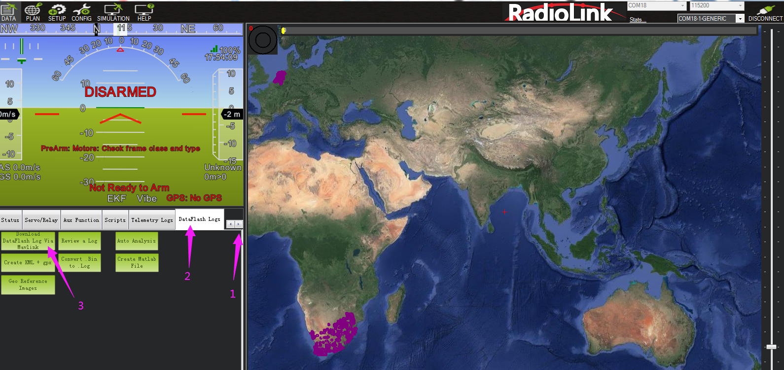
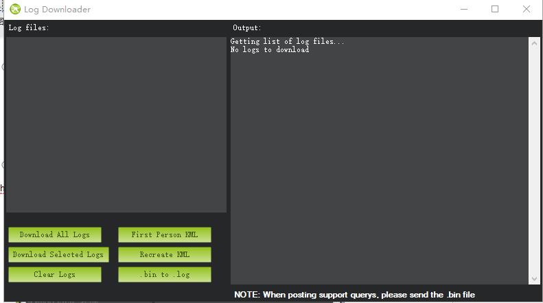
Click the logs you want to view, and click Download these logs to download the selected logs.
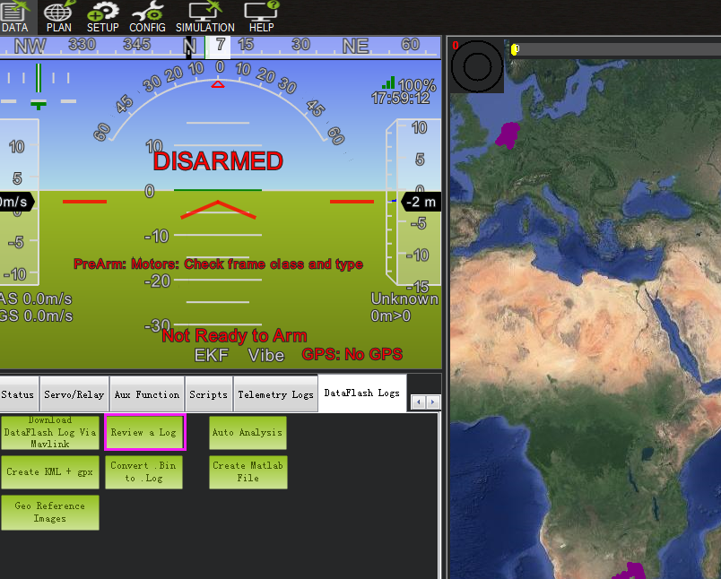
2. Log Check
Click Review a Log and open the log.
Follow steps 1 and 2 in the picture below.
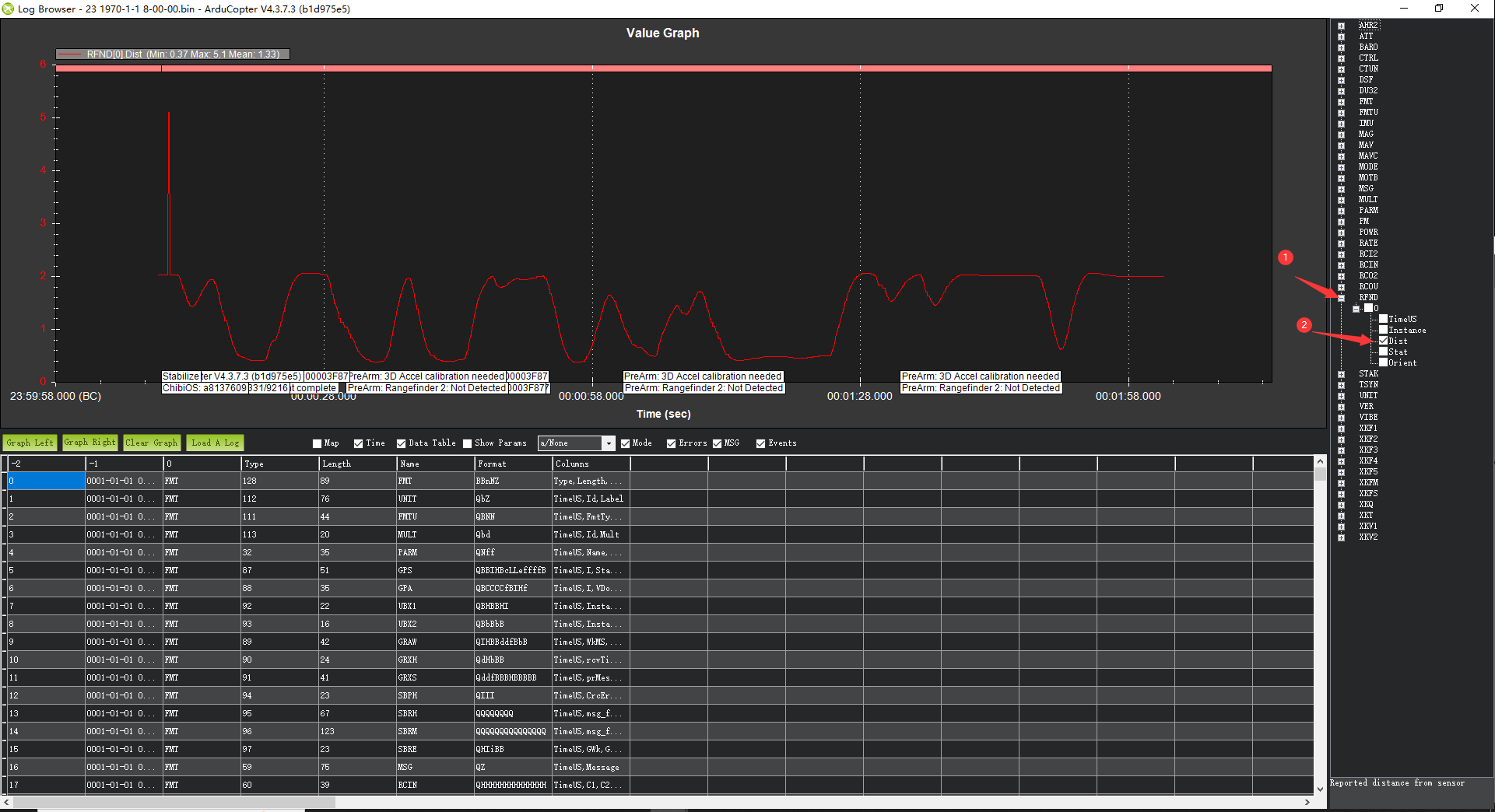
The data shown in the chart is the distance of objects detected by SUI04.