
SAFETY PRECAUTIONS
1.Please do not fly in the rain! Rain or moisture may cause flight instability or even loss of control. Never fly if there is lightning. It is recommended to fly in conditions with good weather (No rain, fog, lightning, wind).
2.When flying, you must strictly abide by local laws and regulations and fly safely! Do not fly in no-fly areas such as airports, military bases, etc.
3.Please fly in an open field away from crowds and buildings.
4.Do not perform any operation under the condition of drinking, fatigue or other poor mental state. Please operate in strict accordance with the product manual.
5.Please be cautious when flying near electromagnetic interference sources, including but not limited to: high-voltage power lines, high-voltage transmission stations, mobile phone base stations and TV broadcast signal towers. When flying in the above-mentioned places, the wireless transmission performance of the remote control may be affected by interference. If there is too much interference, the signal transmission of the remote control and the receiver may be interrupted, resulting in a crash.
6.Please be sure to install the propeller according to the instructions in the manual to avoid installing the reverse propellers and causing a crash.
7.After the flight, be sure the disarm is successful. Please unplug the battery until the propellers stops.
8.When connecting the flight controller to Betaflight Configurator or calibrating the ESC, please make sure that the propellers are not installed on the aircraft.
9.When taking off, please turn on the transmitter first and then the aircraft; After finishing the flight, unplug the aircraft battery first and then power off the transmitter.
10.When arming with success, make sure to stay a certain distance away from the aircraft to ensure safety. Please gently push the throttle when start the flight.
Warning! This product is not a toy and is NOT suitable for children under the age of 14. Adults should keep the product out of the reach of children and exercise caution when operating this product in the presence of children.
Technical Support




Contact RadioLink RL LD-A40 Manual LD-A40 FAQ LD-A40 Tutorials
via Facebook Messenger
If the above communication cannot solve your problem, you can also send emails to our technical support: after_service@radiolink.com.cnThis content is subject to change. Please download the latest version from https://radiolink.com/lda40_user_manual
Packing List
Name | Details | PNP Version | RTF Version |
Fuselage | The drone (Blue/Red available) | 1 | 1 |
Transmitter | RadioLink T12D | 1 | |
Receiver | RadioLink R16SM | 1 | |
Flight Controller | RadioLink F722 | 1 | 1 |
ESC | RadioLink 70A 4-in-1 ESC | 1 | 1 |
Motor | SZ-SPEED 2408-1850KV Motor | 4 | 4 |
Propeller | Gemfan 5-inch Propeller | 4 | 4 |
Battery | Gensace 6S 2100mAh Lipo Battery | 1 | 1 |
RadioLink 2S 1700mAh Lipo Battery | 1 | ||
Charger | HOTA T6 Charger | 1 | |
RadioLink CM210 charger | 1 | ||
Cable | Type-C cable | 1 | 1 |
Hex Wrench | 2.0mm Hex Wrench | 1 | 1 |
Screwdriver Socket Wrench | 1 | 1 | |
Transmitter accessory | T12D Throttle Return Accessory | 1 | |
Package Box | Cardboard Box | 1 | 1 |
Parameters
TakeoffWeight | 1153g(40.67oz) |
Spherical Frame Diameter | 402mm(15.83") |
Material | Carbon Fiber (Frame), Eco-Friendly Modified Polypropylene Material (Ball Shells, Battery Case) |
Signal input supported | CRSF、ELRS、SBUS |
Working Modes | Stabilize mode, Turtle mode |
Flight Time | 5-6 minutes |
LED Strip | With a tail LED light and a ring light strip |
1.Theory of Flight
1.1Transmitter
The two joysticks of T12D correspond to the four basic channels respectively.
Note: All of the following are based onT12D Mode 2 (Throttle on the left stick).
Left joystick
Make the LD-A40 rise or descend by toggling the left stick (THROTTLE) vertically upward or downward and turn clockwise or anticlockwise by toggling the left stick (YAW) to the left or right.
Right joystick
Make the LD-A40 fly forward or backward by toggling the right stick (PITCH) vertically upward or downward and to left or right by toggling the right stick (ROLL) to the left or right.
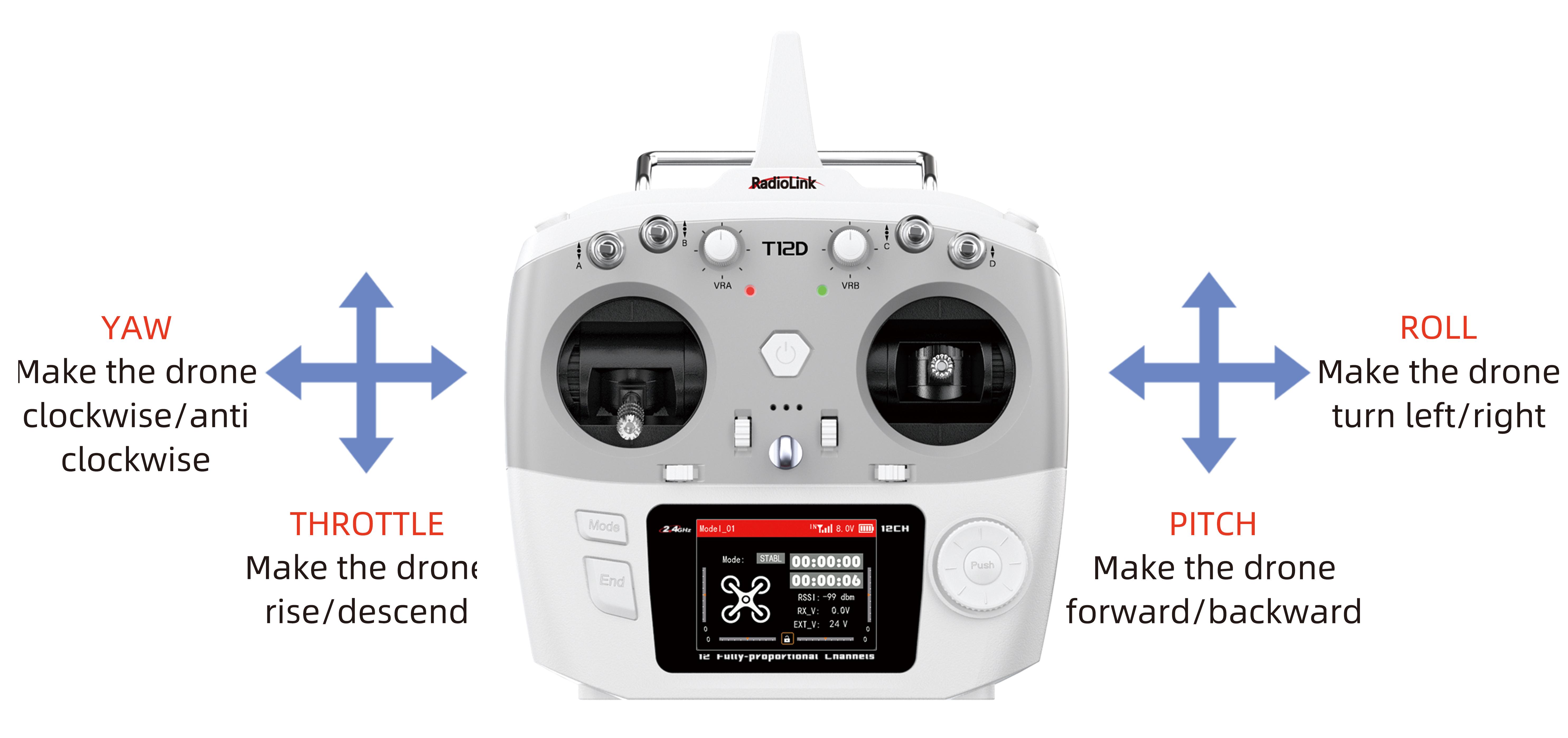
MODE 2
1.2 Joysticks & Flight Movements
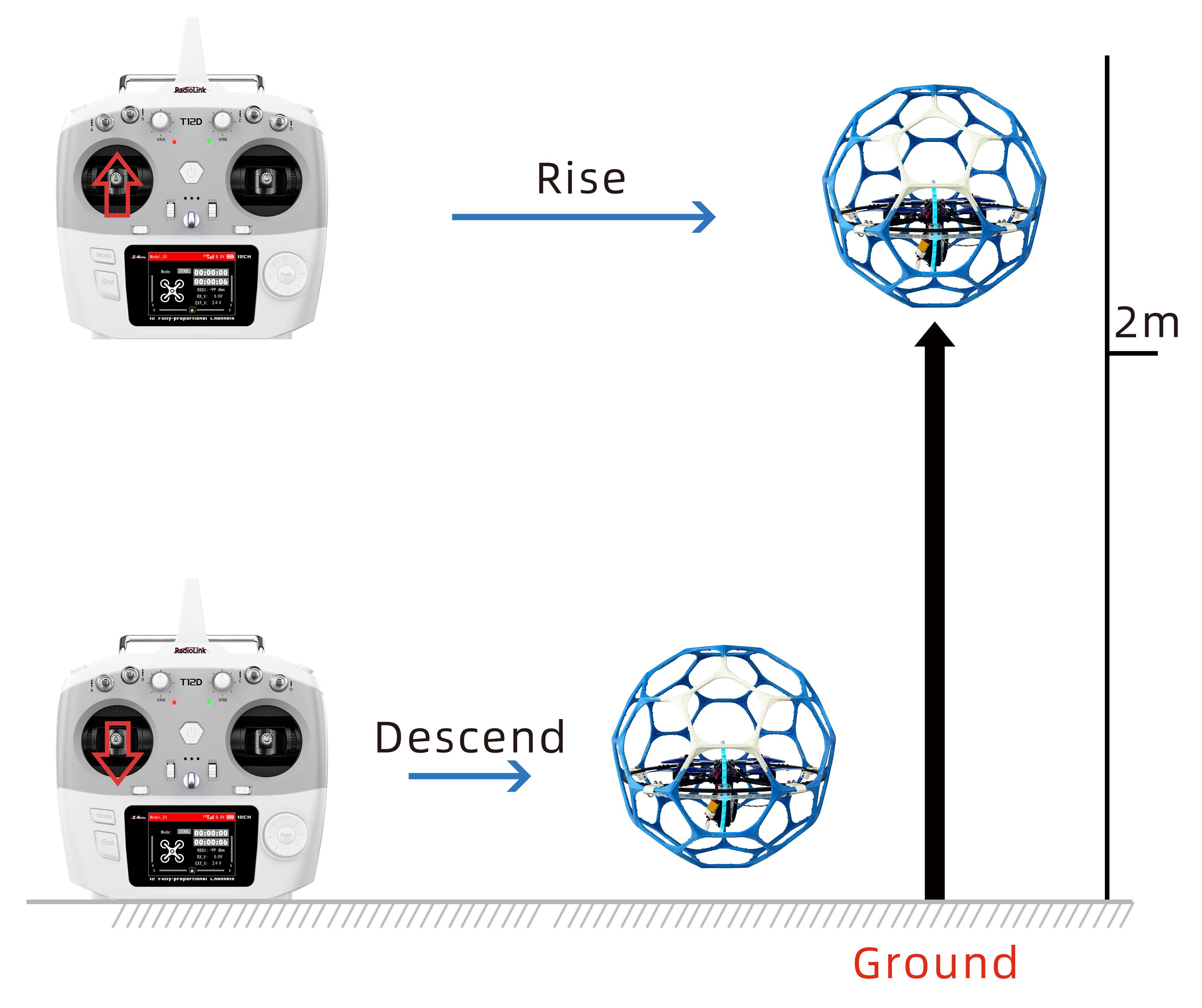
A. Throttle: Rise/ Descend(Note: Take T12D mode 2 as an example)
Toggle the throttle stick (on the left) vertically upward and LD-A40 will rise and toggle the throttle vertically downward, then LD-A40 descends.
B. Yaw: Clockwise/Anticlockwise
Toggle the yaw stick (on the left) to the left and LD-A40 will turn anticlockwise and toggle the yaw stick to the right, then LD-A40 turns clockwise.
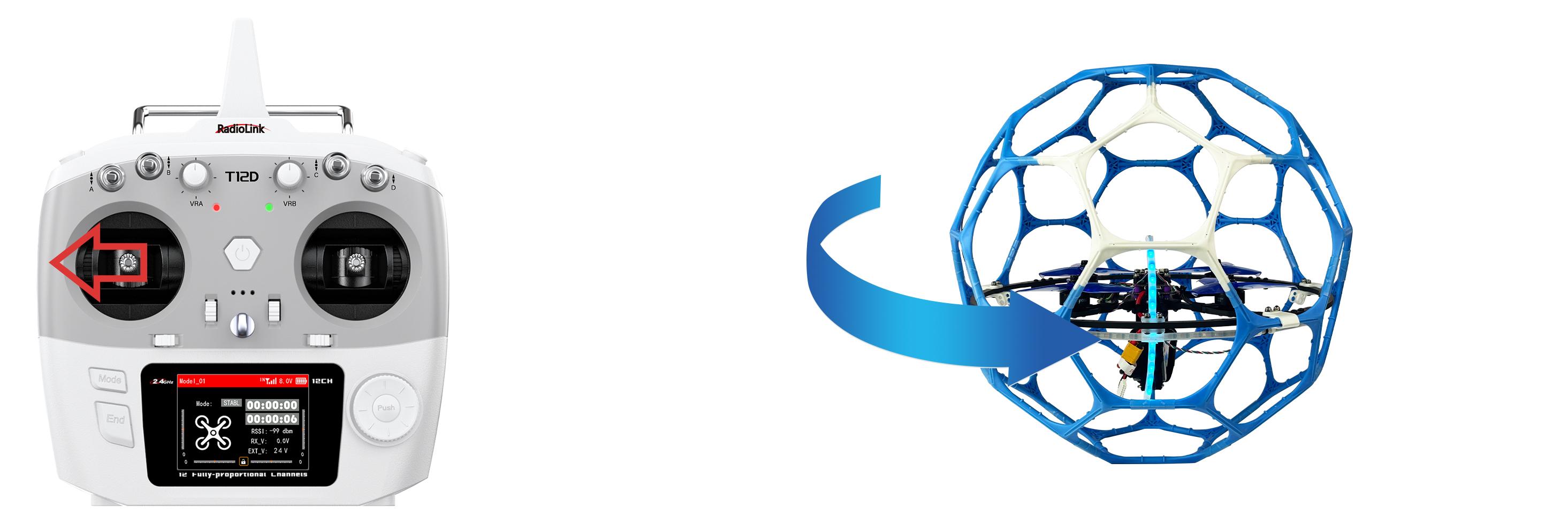
Yaw stick to the left, LD-A40 turns anticlockwise
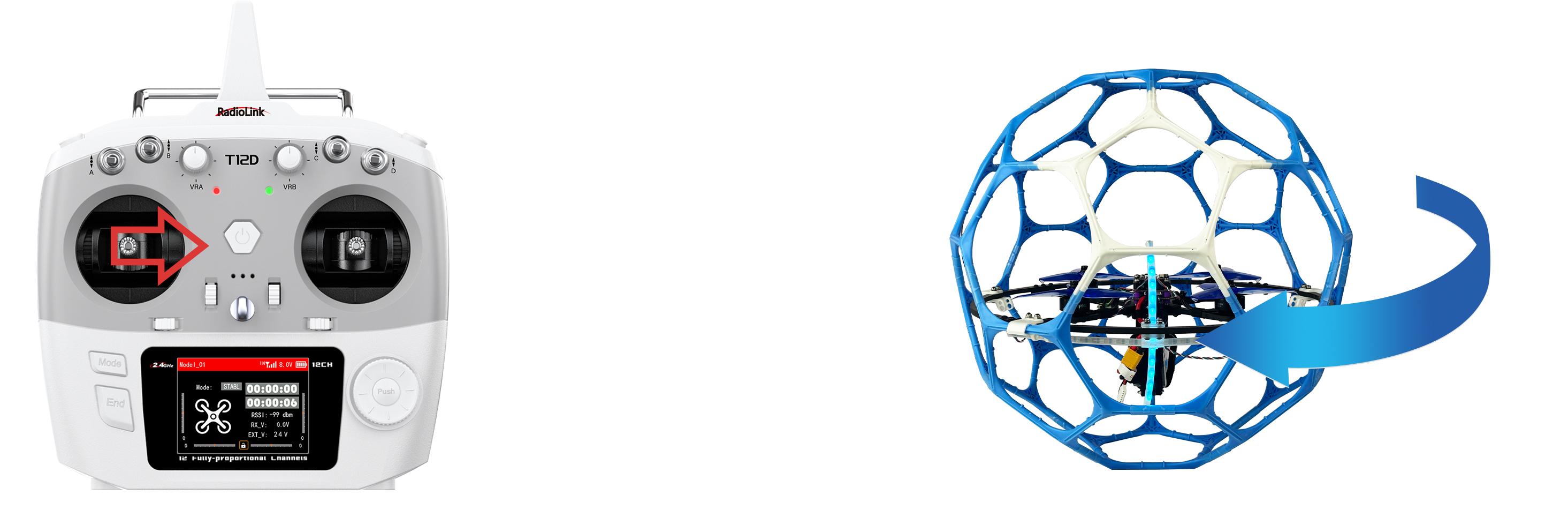
Yaw stick to the right, LD-A40 turns clockwise
C. Pitch: Forward/Backward
Toggle the pitch stick (on the right) vertically upward and LD-A40 will fly forward and toggle the pitch stick vertically downward, then LD-A40 flies backwards.
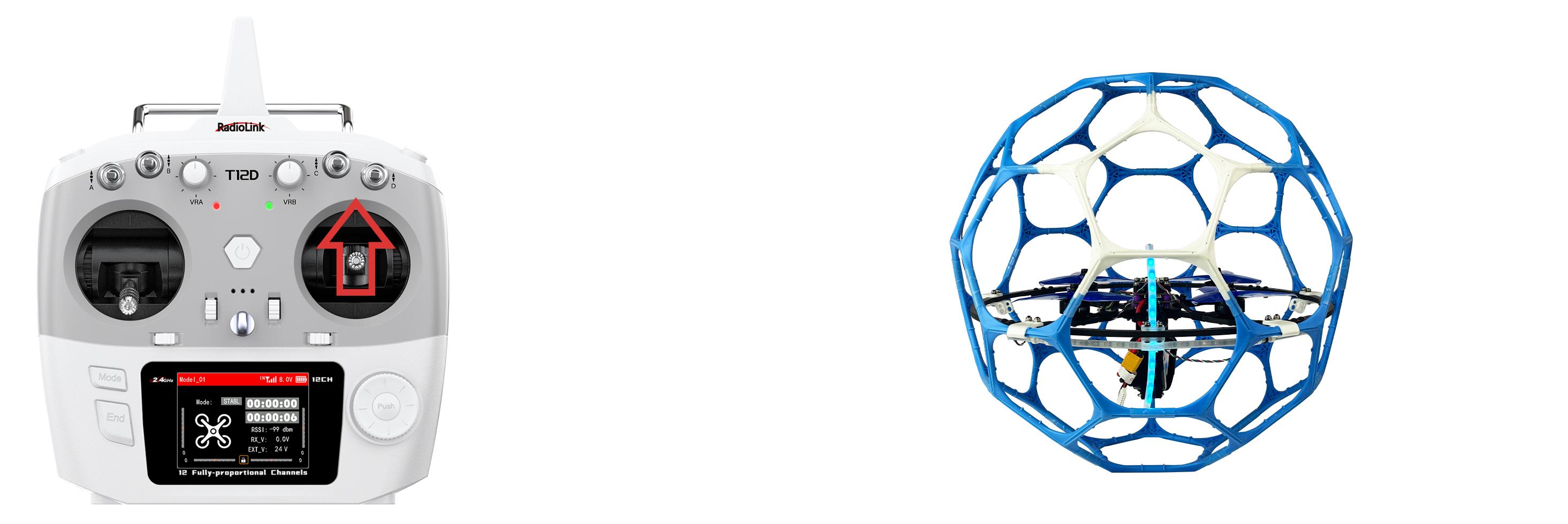
Pitch stick upward, LD-A40 moves forward
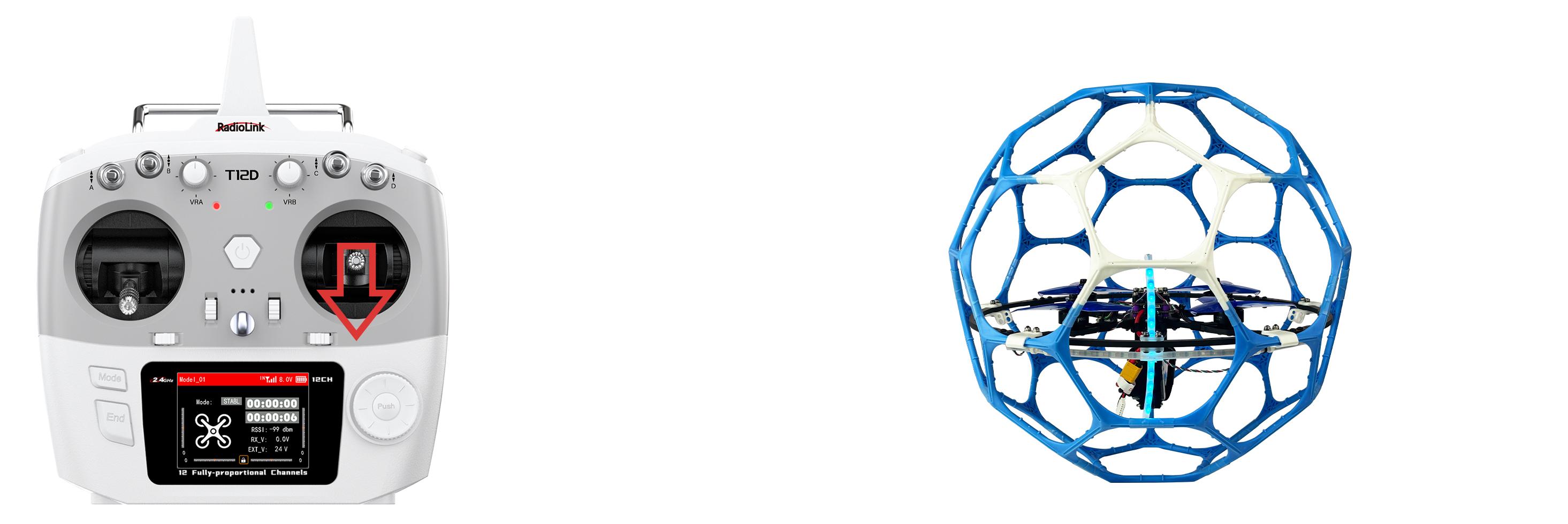
Pitch stick downward, LD-A40 moves backward
D. Roll: Right/Left
Toggle the roll stick (on the right) to the left and LD-A40 will fly to the left side and toggle the roll stick to the right, then LD-A40 will fly to the right side.
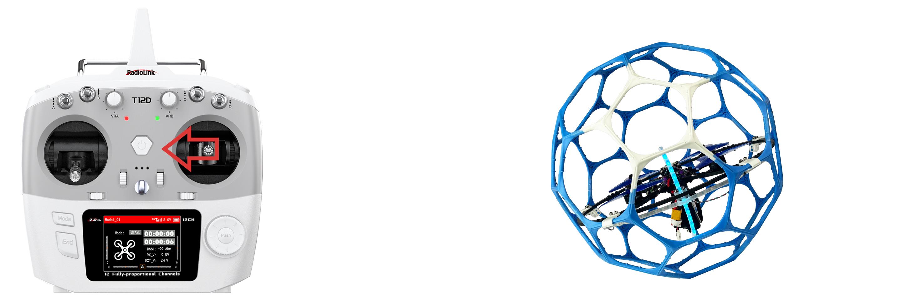
Roll stick to left, LD-A40 fly to the left side
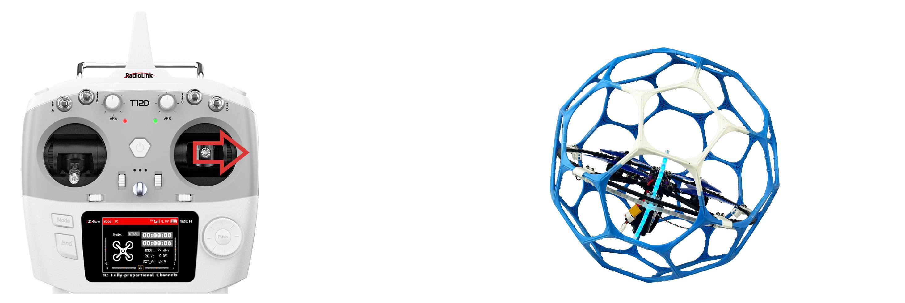
Roll stick to right, LD-A40 fly to the right side
2.Flight Controller Channel Introduction
Channel | Introduction |
CH1 | Roll |
CH2 | Pitch |
CH3 | Throttle |
CH4 | Yaw |
AUX1 | Disarm/Arm |
AUX2 | Stabilize mode |
AUX3 | Turtle mode |
3.Transmitter Switch Introduction
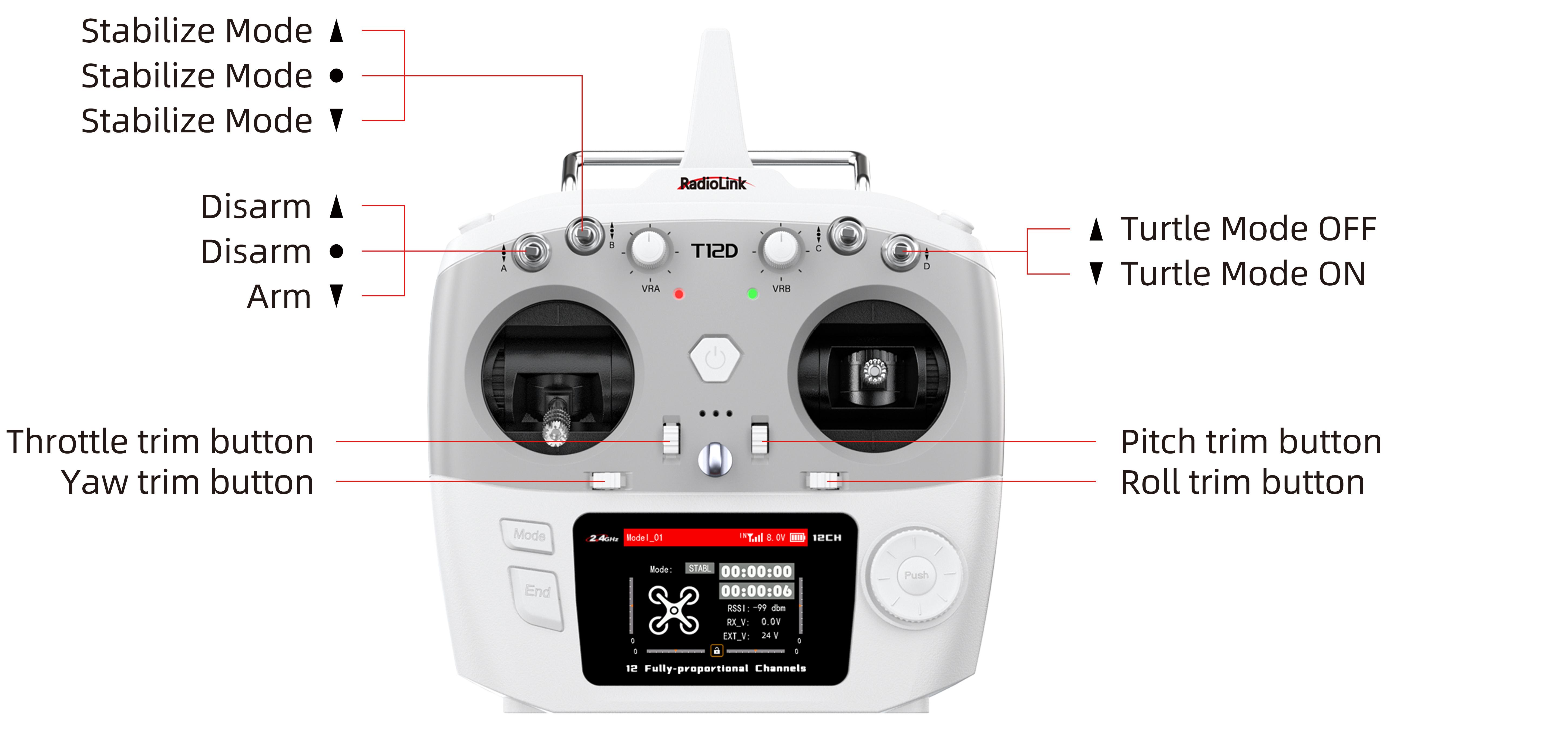
LD-A40 comes with RadioLink T12D transmitter. Here is the introduction of the switches of T12D:
SWA: Push it up or to the middle position to disarm the drone. Push it down to arm the drone. Corresponding to AUX1 of the flight controller.
SWB: Stabilize mode. Corresponding to AUX2 of the flight controller.
SWD: Push it up to turn off the turtle mode. Push it down to turn on the turtle mode. Corresponding to AUX3 of the flight controller.
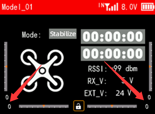
When the trim values on the screen of T12D are not 0, please adjust the trim values to 0 by using the four trim buttons (as shown above). For more details, please refer to the detailed manual of T12D: https://www.radiolink.com/t12d_manual
4.Arm and Disarm LD-A40
Arm LD-A40
Power on LD-A40 with the 6S lipo battery that comes with it. After powering it up, place LD-A40 on the ground and keep it stationary for self-check. The motor will emit a piece of music during the self-checking. When you hear a short music, the self-checking is complete.
Make sure the throttle is at the lowest position. Push SWA down to the lowest position, and the propellers start to rotate at idle speed indicates arm successful.
Note: The throttle stick must be in the lowest position when arming.
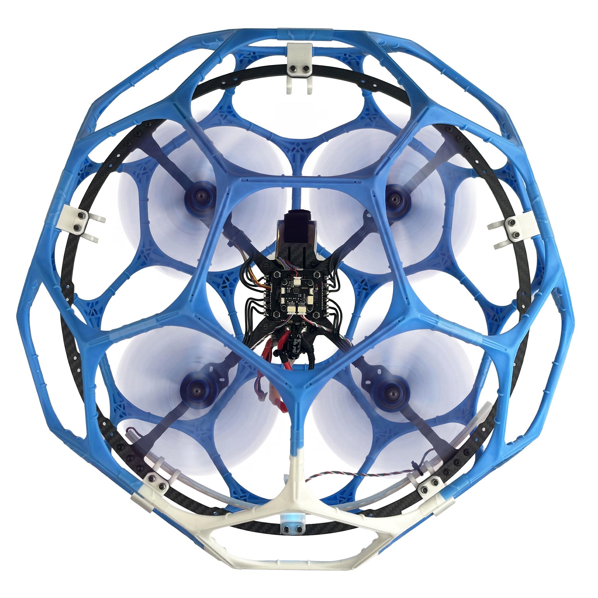
LD-A40 propellers start to rotate at idle speed indicates arm successful
Disarm LD-A40
When the flight is finished, push up SWA to disarm LD-A40. LD-A40 propellers stop rotating indicates disarm successful.
Note: During the flight, the motors/propellers will stop immediately if SWA is pushed up. Please pay attention to avoid hitting people and damaging valuables.
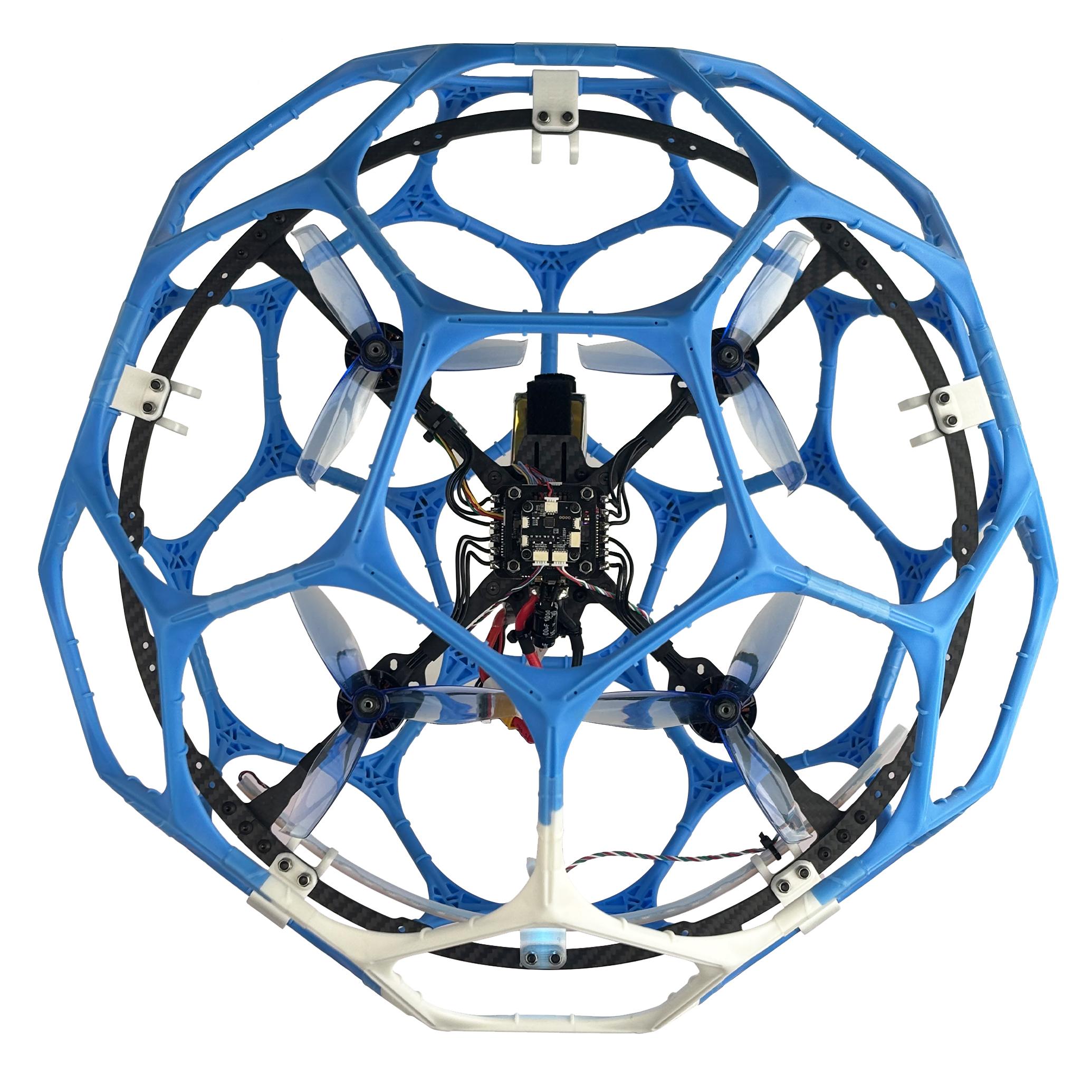
LD-A40 propellers stop rotating indicates disarm successful
5.Two Working Modes
5.1Stabilize mode
In Stabilize mode, the throttle corresponds to the drone power. The more the throttle stick is pushed up, the greater the climbing power. If you want the drone to maintain the same altitude, the pilot needs to practice for a period of time to achieve it through flight operations.
5.2Turtle mode
If the drone suffers a collision or operational error that causes it to flip over—leaving it unable to fly up—you can activate turtle mode to flip it back, so it can take off. First, push SWA up to disarm the drone, and the propellers stop rotating. Next, push the throttle stick to the lowest position. Then, push SWD down to activate the turtle mode. Finally, Push SWA switch to the lowest position to arm the drone. If the propellers remain stationary, you have successfully entered the turtle mode. If the propellers start to rotate at idle speed instead, it merely indicates that the drone is armed. Please repeat the above steps to activate the turtle mode.
After the turtle mode is activated, move the roll or pitch stick to flip the drone. After the drone flips back to the level, push SWD up to exit the turtle mode. Push SWA up and then down to arm the drone, and take off.
Note: When turning on/off the turtle mode, the throttle stick must be at the lowest point. Otherwise you cannot turn on/off the turtle mode.
6.LED Strip Switch
LD-A40 has a tail LED light and a ring light strip. They have 7 colors that can be switched, namely red, green, blue, yellow, purple, cyan and white. Short press the button on the light board to switch their light color or turn off the light.
The light board socketsof LD-A40 are as follows:

Note: There are 3 light switch buttons on the light board, 2 of which work (including the tail LED light switch button and the ring light strip switch button), and the remaining one does not work. You can press the 3 light switch buttons to confirm which two buttons work.
7. Low Battery Alarm
LD-A40RTF version comes with a RadioLink R16SM receiver. R16SM supports model battery telemetry function. During the flight, the battery voltage of the drone can be viewed on the screen of T12Dtransmitter. The default alarm voltage for the power battery is 22V. When the battery voltage is lower than 22V, T12D will issue an alarm. Please land the drone in time to replace the battery. If flight continues, the power of the drone will diminish significantly—eventually rendering it unable to fly. Such a scenario constitutes a state of severe battery over-discharge. It is strongly recommended to land and replace the battery as soon as the voltage reaches 22V. After landing, please disconnect the power and replace the battery in time to avoid over-discharge of the battery.
Note: If you want to modify the alarm voltage, please refer to the detailed manual of T12D: https://radiolink.com/t12d_manual
8. Motor and Propeller Installation
To make the drone fly, motors usually rotate clockwise (CW)/counterclockwise (CCW) with the propellers.It is very important to make sure about the rotation direction as below when installing motors. Otherwise, the drone would fail to take off.
Motor and propeller installation can be skipped as LD-A40 is already assembled by factory default. If any of the motors is worn out and needs to be replaced, it is essential to identify the correct motor/propeller rotation. Please follow the below picture to install the motor and propeller.
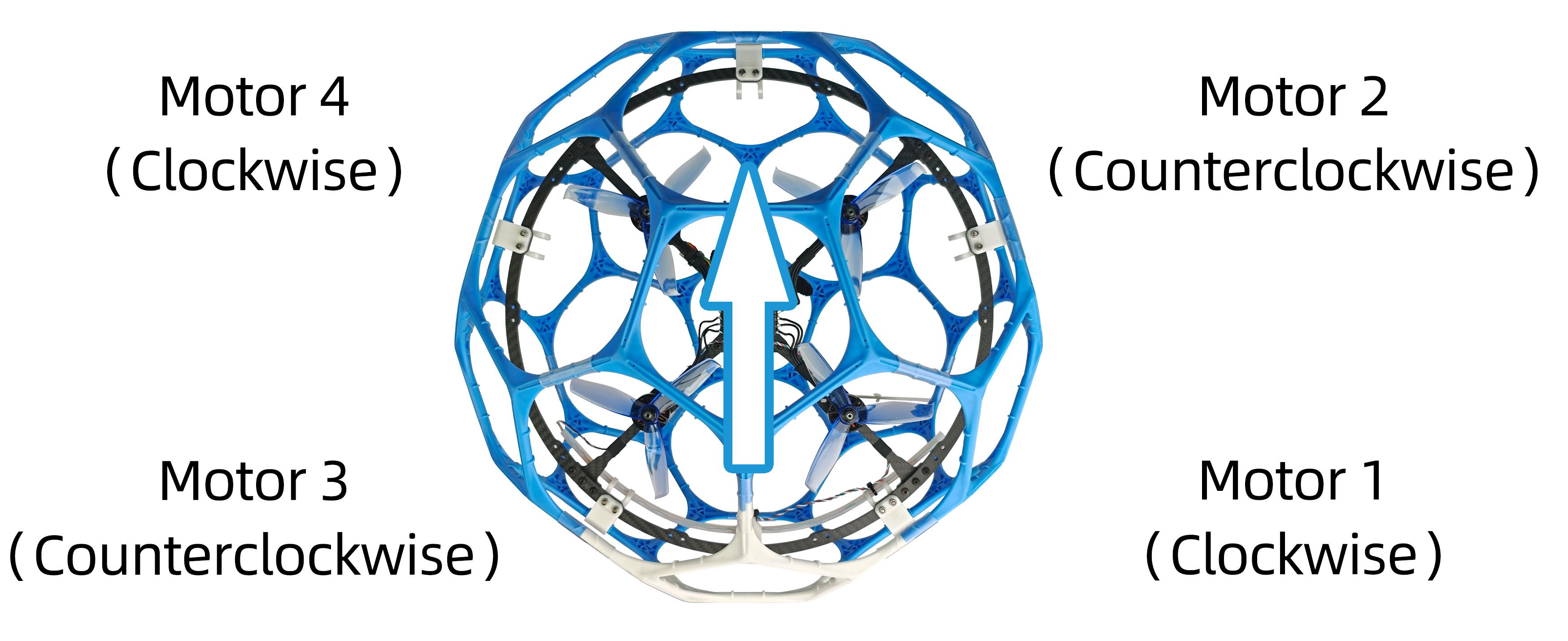
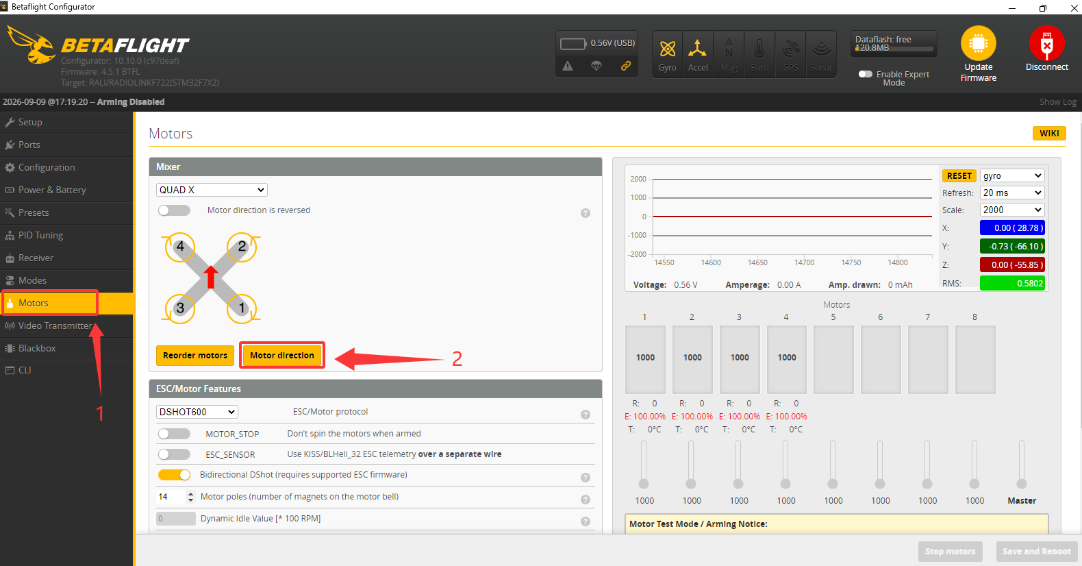
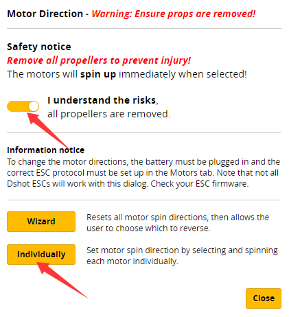
If the motor rotation direction is incorrect, you must adjust it. First, remove the propellers and power on the drone using the battery. Connect the flight controller to Betaflight Configurator. After the connection, click Motors--Motor direction. When the pop-up appears, check the box acknowledging the risks. Then, select "Individually". In the resulting interface, press and hold the buttons for motors ①, ②, ③, and ④ one by one to verify their rotation directions: Motor ① and ④ should rotate clockwise, while motor ② and ③ should rotate counter-clockwise. If you detect an incorrect rotation direction, click the "Normal" or "Reversed" to change the motor's rotation.
9. Binding (R16SM)
LD-A40RTF version comes with T12D transmitter and R16SM receiver (as shown below).
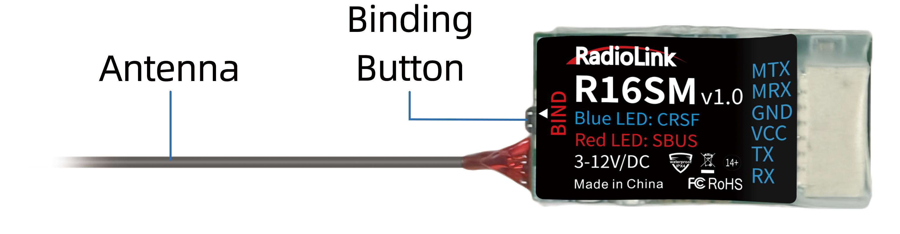
If it is the RTF version purchased, there is no need to bind because the binding between the transmitter and R16SM receiver is complete by factory default. In addition to T12D, R16SM is also compatible with T16D/T8FB/T8S. If you want to change the transmitter, binding between the transmitter and receiver needs to done first.
Here are the binding steps for RadioLink transmitter and receiver:
① Place the transmitter and receiver(installed on LD-A40) close to each other within 50 centimeters.
② Power on the transmitter and the receiver.
③ There is a black binding button on the side of the receiver. Press it for more than 1 second. When the LED starts flashing, meaning binding process has started. Note: If there are multiple devices of the same model in the same location, it is recommended to turn off the other devices first, and then binding them.
④ The binding is complete when the LED is always on means the binding is complete.
Note: Please always make sure the LED of R16SM is blue, meaning CRSFprotocol. If the LED is red (SBUS working mode), please press the binding button once to change it to blue.
For transmitter and receiver from other brands, please refer to its detailed manual for binding steps.
10.Charger
LD-A40 RTF version is packed with HOTA T6 smart charger and RadioLink CM210 charger to charge the battery.
HOTA T6 smart charger
Specifications
InputVoltage | DC 10~30V /PD3.0/QC20V | ChargeCurrent | DC15A /PD5A |
ChargePower | 0.1~15A@300W | PowerSupply | 0.1-15A@5-29V |
PD90W | Discharge Current | 600mA | |
DischargePower | InternalDischarge:30W(Balanceport10W) | Temperature | -20~60°C |
External Discharge:700W | OperatingTemperature | 0~40°C | |
BatteryType | Lead Acid(Pb):1~12S(2~24V)Eneloop:1~14S | ScreenSize | 260000colors |
Battery Type | LiHV/LiPo/LiFe/Lilon/Lixx: 1~6S NiZn/NiCd/NiMH: 1~14S Smart Battery: 1~6S Lead Acid(Pb): 1~12S(2~24V) Eneloop: 1~14S | Dimensions | 70.5mmx49.5mmx30.5mm |
NetWeight | 93g | ||
ProtectionFunction | Temperature protection, time protection, capacity protection, input reverseprotection, outputprotection, shortcircuitprotection, outputovercurrentprotection, output overvoltageprotection, overchargeprotection | ||
Introduction
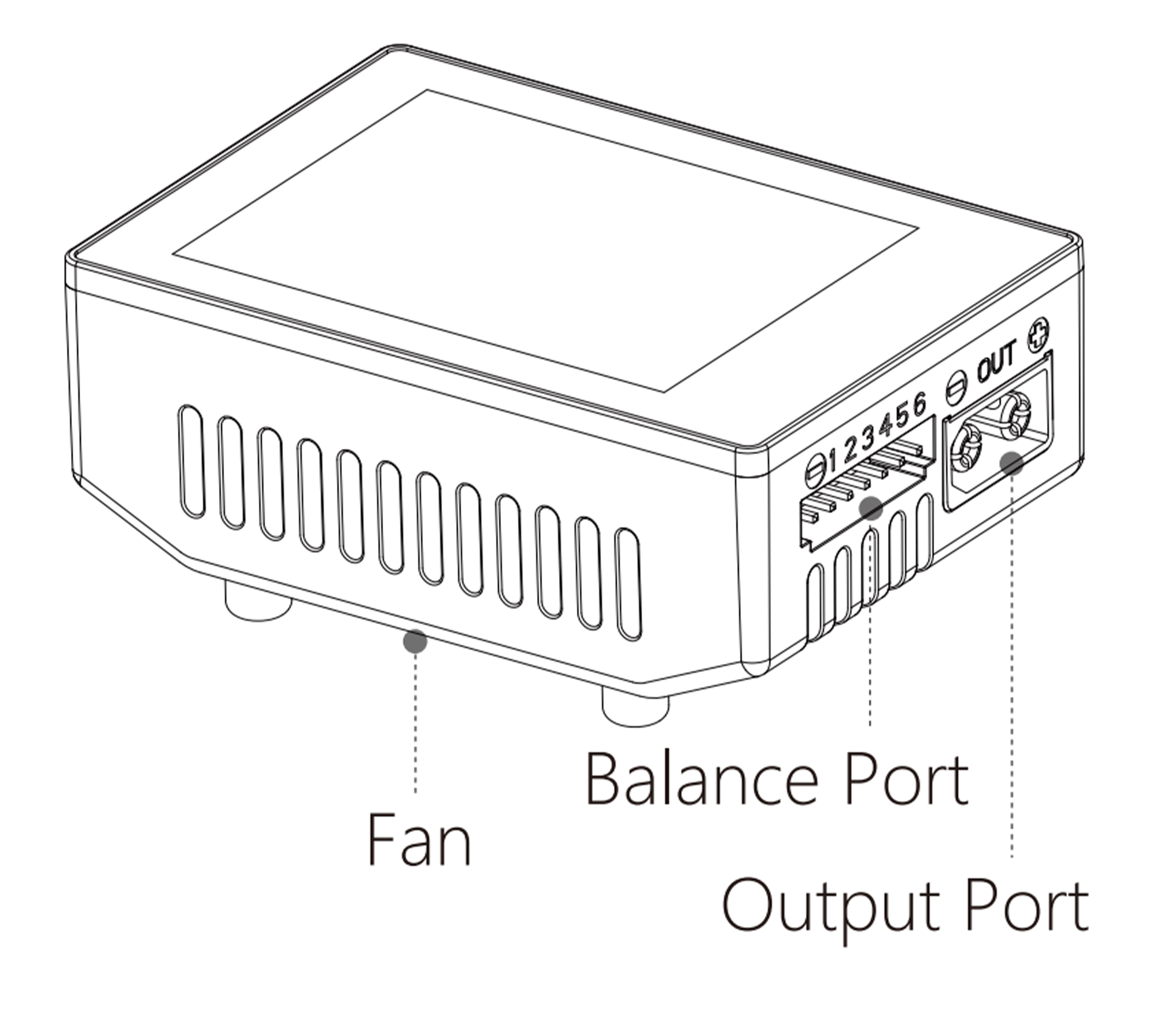
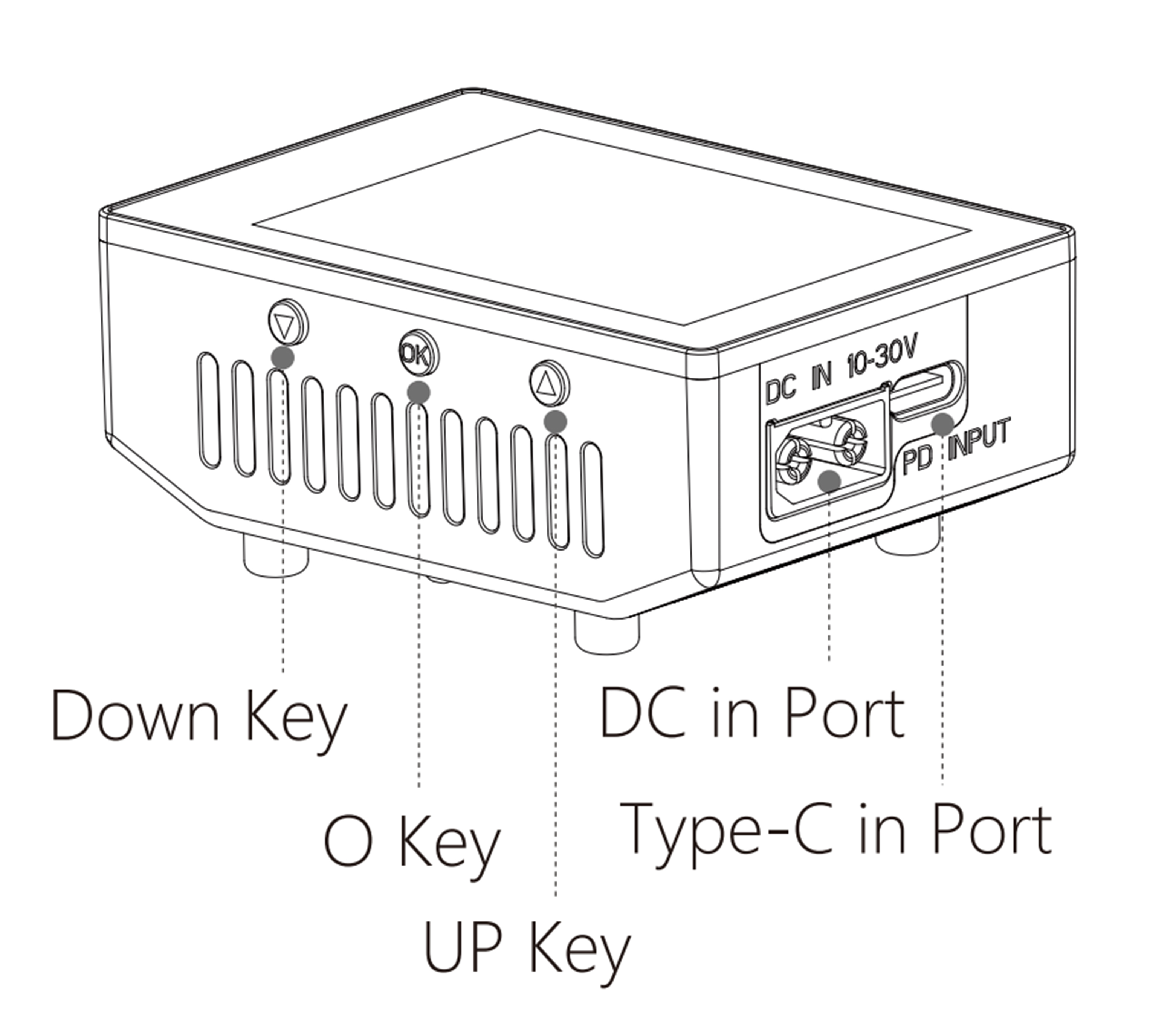
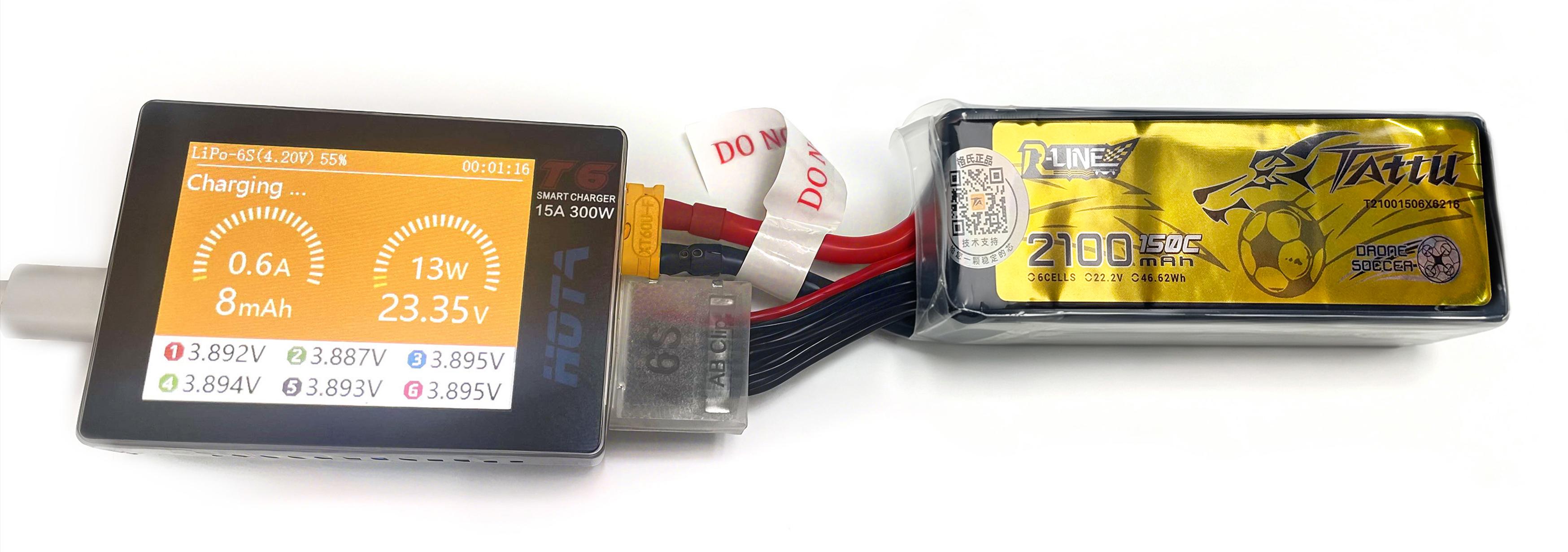
The Connection between the Charger and the Battery
Warnings and Safety Notes
(1)Do not use the charger in an unattended manner, in case of any functional abnormity, please stop using it and refer to the manual.
(2)Keep the charger away from dust, humidity, rain and high temperature, as well as avoid direct exposure to sun and intense vibration.
(3)Input voltage of the charger is 6.5-30V DC. When connecting the power supply, make sure that the input voltage match the operating voltage range of the charger.
(4)Please place the charger on a heat-resisting, non-flammable and insulating surface. Do not use it by placing it on the car's seats, carpet or other similar place. Keep inflammable and explosive objects away from operation areas of the charger.
(5)Make sure the heat emission hole at the side of the charger is uncovered while in use, and ensure the cooling fan smoothly extracts heat.
(6)Please fully understand the charging and discharging characteristics as well as the battery's specifications. Additionally, set up proper charging parameters in the charger. Incorrect setting of parameters can cause damage to the charger and battery and/or result to disastrous consequences such as fire or explosion.
(7)When charging or discharging is completed, please press the O key to terminate current task, and remove the battery when charger shows the standby screen.
Recommended Connected Way
(1)Connect the power supply, wait for self-checking to be completed ;
(2)Connect the battery to the charger under standby interface ;
(3)Set up task parameters applicable to your battery through the display and touch key ;
(4)Enjoy.
Operative Skills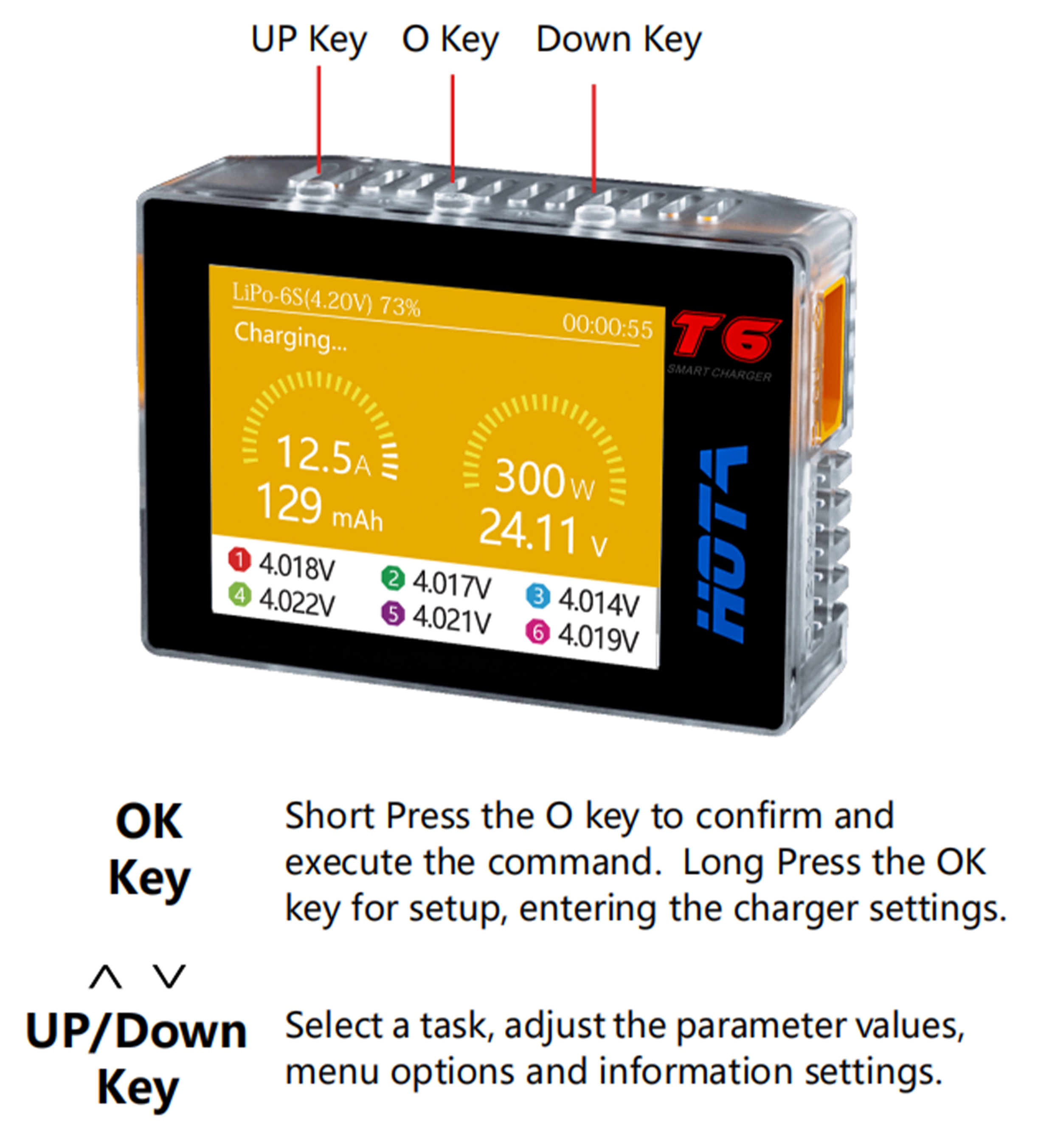
(1)Connect power supply to the charger's PD or DC port, wait for the system to complete the self-checking. In standby interface, connect the battery to the charger. Short Press OK key to pop up the“Task Settings”menu, press the Up/Down key to select the operation task and adjust the task parameters, short press OK key to start the task.
(2)When the task is being executed, you can short press the OK key to pop up the“Adjust Task”menu to adjust the task's current or stop the task. long Press the OK key to quickly end the current task .
(3)In standby interface, long press the OK key to enter the“Charger Settings”menu.
Charger Settings
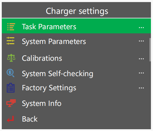
In the standby interface, long press the O key to pop up the“Charger Settings”menu. The menu items are as follows:
Task Parameters | Adjust Safety Timer, Max Capacity, End Current and other parameters |
System Parameters | Adjust Language, Regen. Discharge, input power, Volume and other parameters |
Calibrations | For data calibration |
System Self-checking | Start self-checking of the charger |
Factory Settings | Restore all parameters to factory settings(User calibration data cleanup) |
System Info | Display system information, serial number |
Back | Exit“Charger Settings” |
For more details of the detailed operating instruction of HOTA T6 smart charger, please download it from the link: https://www.radiolink.com/manuals_download
CM210 charger
Specifications:
Size: 40.5*21*15 mmWeight: 9g
Input Voltage: 5VSupporting Battery: 2S LiPo battery
Charging Precision: 0.02VCharging Voltage: Max. 4.2V for each battery cell
Charging Current: 1.5ABalance Current: 0.8A
Max. Output Power: 20WPower Supply Input Port: USB Type-C Input
Charging Port Interface: 3P XH2.54 port
Working Modes: Charging Mode, Balance Mode, Repair Mode (Self-adaptive, with no need to set it)
The connection of CM210, battery, and the cables is as shown below:

Instructions for using CM210 charger:
1.Insert one end of the standard USB cable into the Type-C input port of the CM210 charger (as shown in the picture above), and then connect the other end of the USB cable to power supply equipment such as power bank, computer, mobile phone adapter, etc.. After the right connection, the red LED indicator will be always on.
2.Insert the balance port of the standard 2S lithium battery of D460 into the charging port of CM210 (as shown in the picture above). Then the green LED indicator starts flashing, which means it starts to charge the battery. (Note: The green LED indicator flashes during the charging to indicate normal charging; If the red LED indicator flashes during the chargingto indicate abnormal charging. Please reconnect battery and cable to troubleshoot the abnormality.)
3.When all four LED indicators turn solid green, the battery is fully charged, and the charger will automatically stop charging.
4.Remove the battery and then disconnect the power supply.
CM210 LED indicator status:
LED color | Status | Meaning |
Red | Flash | The charger detects abnormality. |
Always on | No battery is connected. | |
Green | All four green LEDs flash once. | The charger is powered on. |
The first green LED flashes, and the other LEDs are off. | The battery voltage is lower than 7.4V. | |
The first green LED is always on, and the second green LED is flashing. The other LEDs are off. | The battery voltage is lower than 7.8V. | |
The front two green LEDs are always on, and the third green LED is flashing. The other LEDs are off. | The battery voltage is lower than 8.2V. | |
The front three green LEDs are always on, and the fourth green LED is flashing. The other LED is off. | The battery voltage is lower than 8.4V. | |
All four green LEDs are always on. | The battery is fully charged. |
Troubleshooting for CM210 charger:
1. After the charger is powered on, the red light flashes just after inserting the battery or within one minute.
(1)The current detection resistor is burned out, and the MCU detects that the current is too large.
(2)The switch tube is damaged, so it is unable to switch normally. There is no current output or the output current of the power supply is too small.
2. After the charger is powered on, insert the battery and charging works normally for a period of time, and then the red light flashes.
(1)The output current of the power supply is too small, or the battery is damaged.
Solution: Replace the power supply or battery to charge it again, if the abnormal phenomenon still occurs, the charger is damaged.
11. Accelerometer Calibration
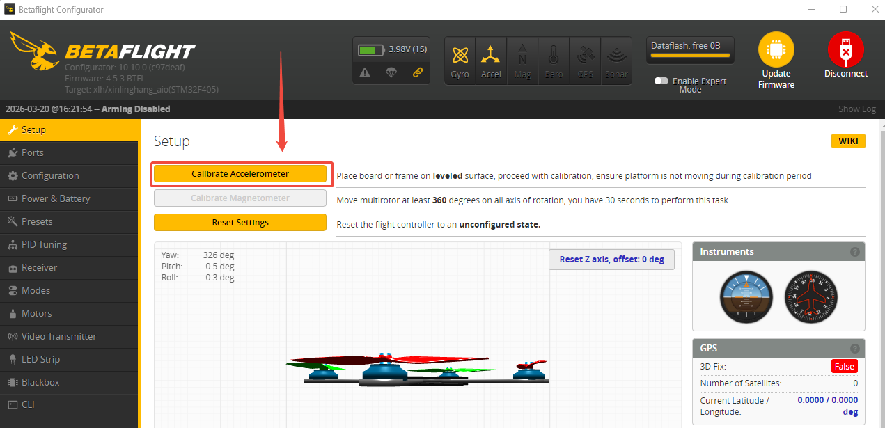
Accelerometer calibration has been doneby factory default. You can flyit directly without calibration. If you have dismantled the frame or the flight controller, you need to calibrate the accelerometer. The installation direction of the flight controller must be the same as the factory installation direction, otherwise it will be out of control after arming. Please disconnect the power battery during accelerometer calibration, and power on the flight controller with a Type-C cable. Here are the steps of accelerometer calibration:
Connects the flight controller to the computer via a Type_C cable. Open Betaflight Configurator. Click CONNECT on the upper right corner. After the connection, click Setup--Calibrate Accelerometer.
12. The Receiver Connection for LD-A40 PNP
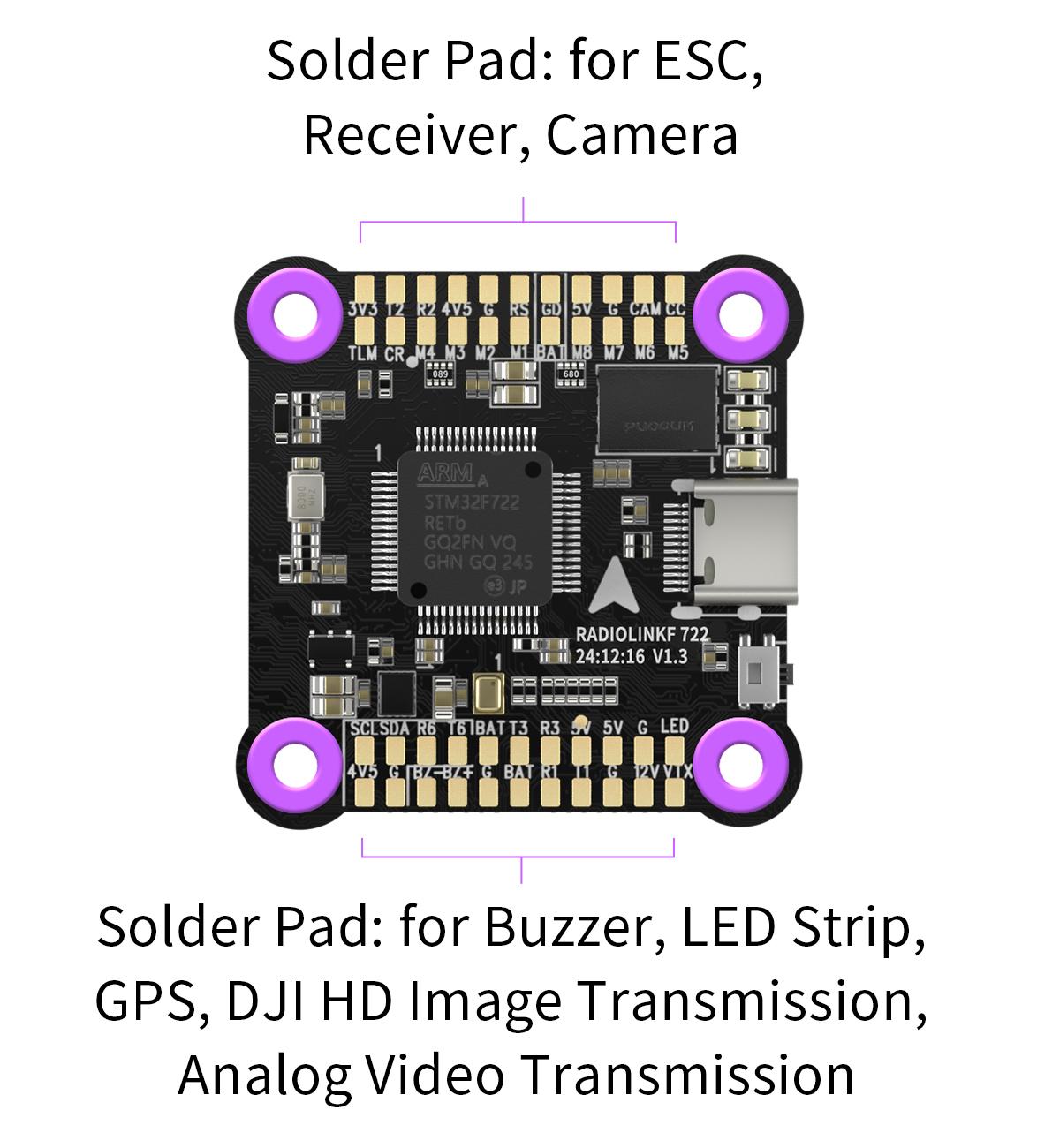
For LD-A40 PNP version, uses need to prepare the transmitter and receiver. The receiver needs to connect to the flight controller. Here is the introduction of the flight controller of LD-A40:
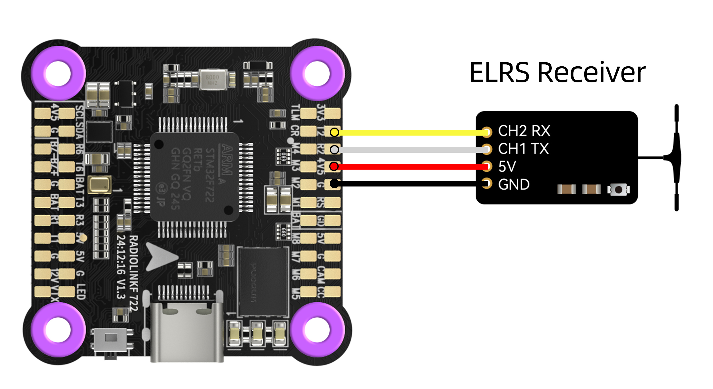
Soldering Pad Definition
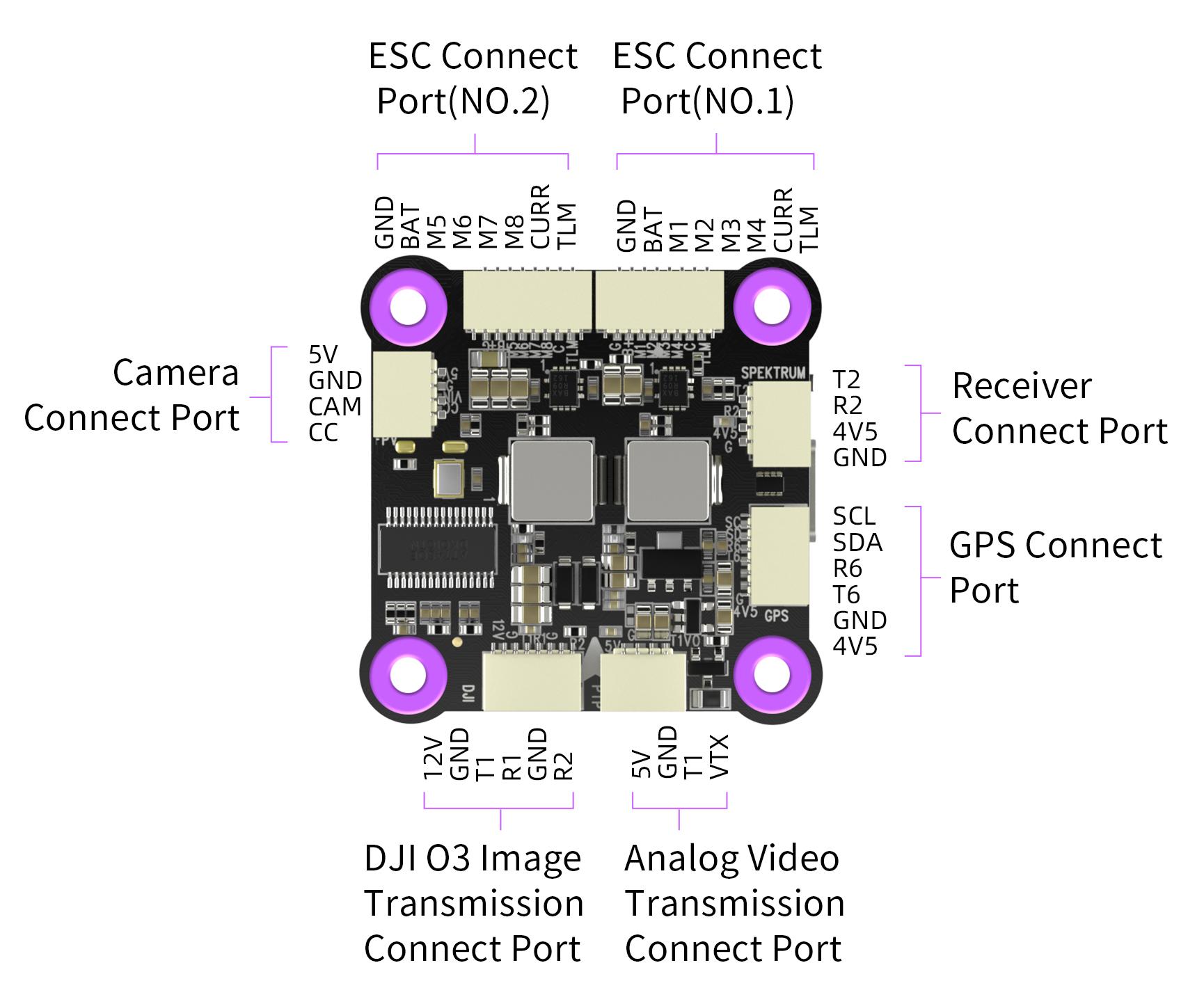
Socket Interface Definition
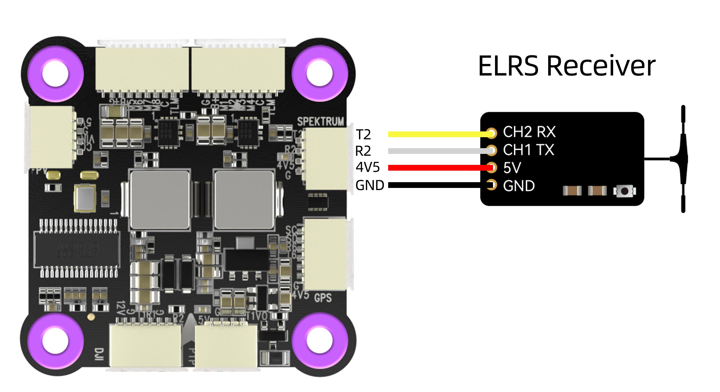
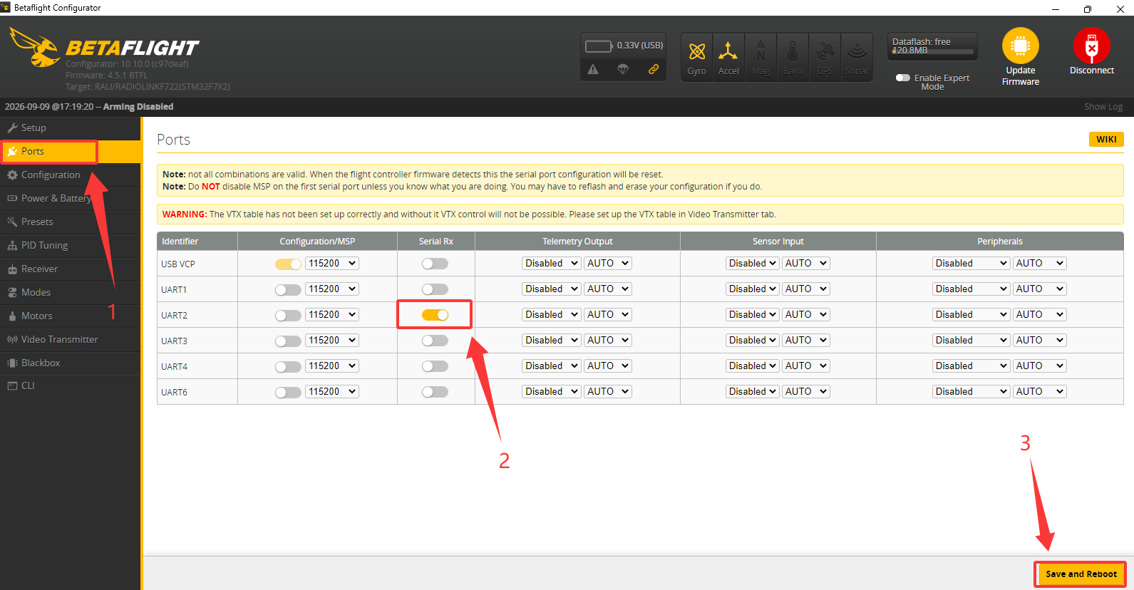
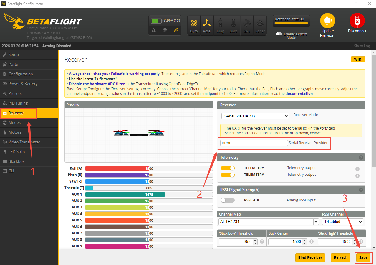
If ELRS receiver is used with LD-A40, you can connect or solder ELRS receiver to the serial 2 on the flight controller (as shown below). Ensure that the receiver's TX pin is connected to the flight controller's RX pin and the receiver's RX pin is connected to the flight controller's TX pin. Then connect the flight controller to Betaflight Configurator. After the connection, click Ports, turn on the Serial RX of UART2 and click Save and Reboot. Then click Receiver, set CRSF for Serial Receiver Provider, and save the modifications. The steps are shown below:
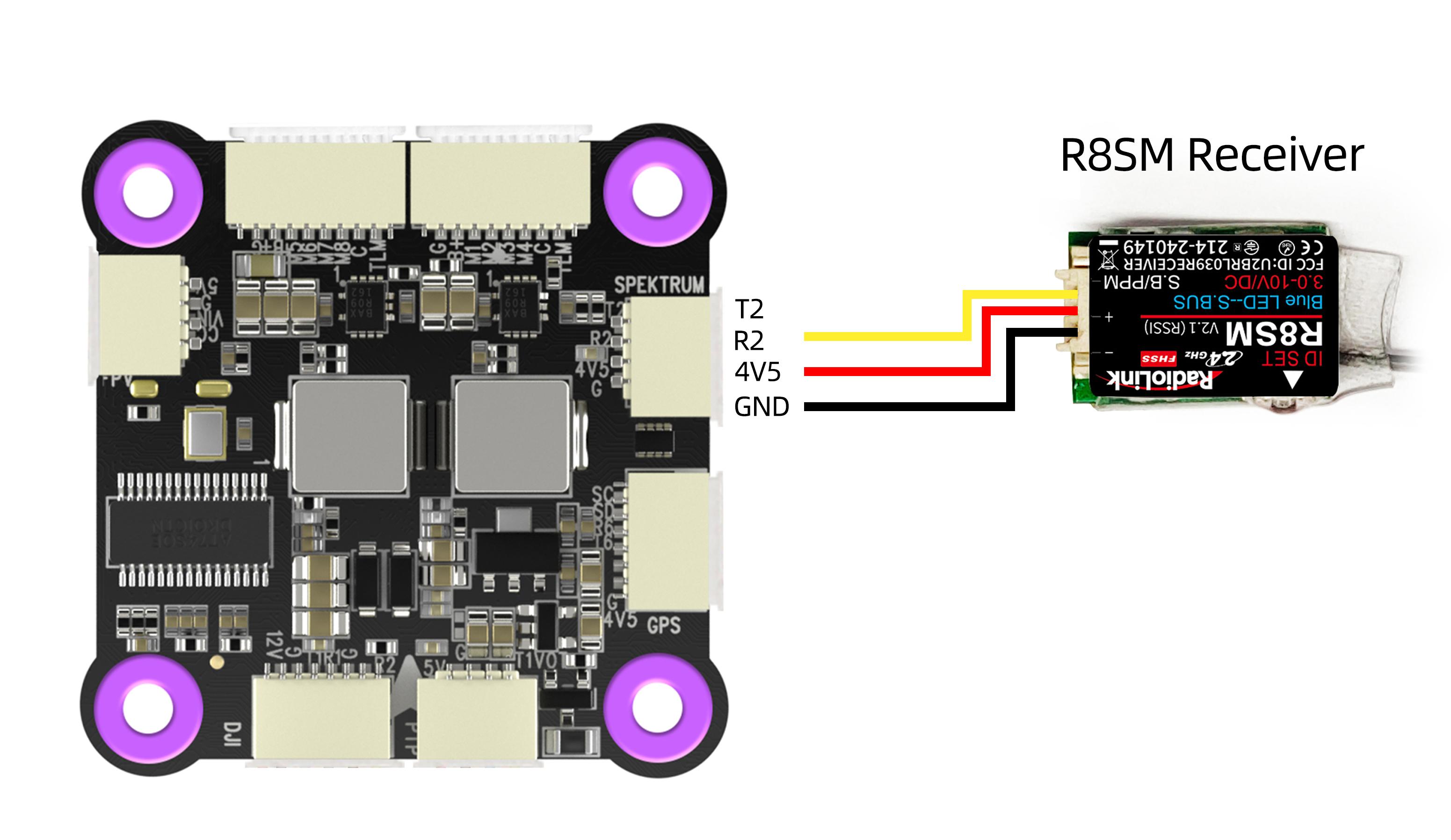
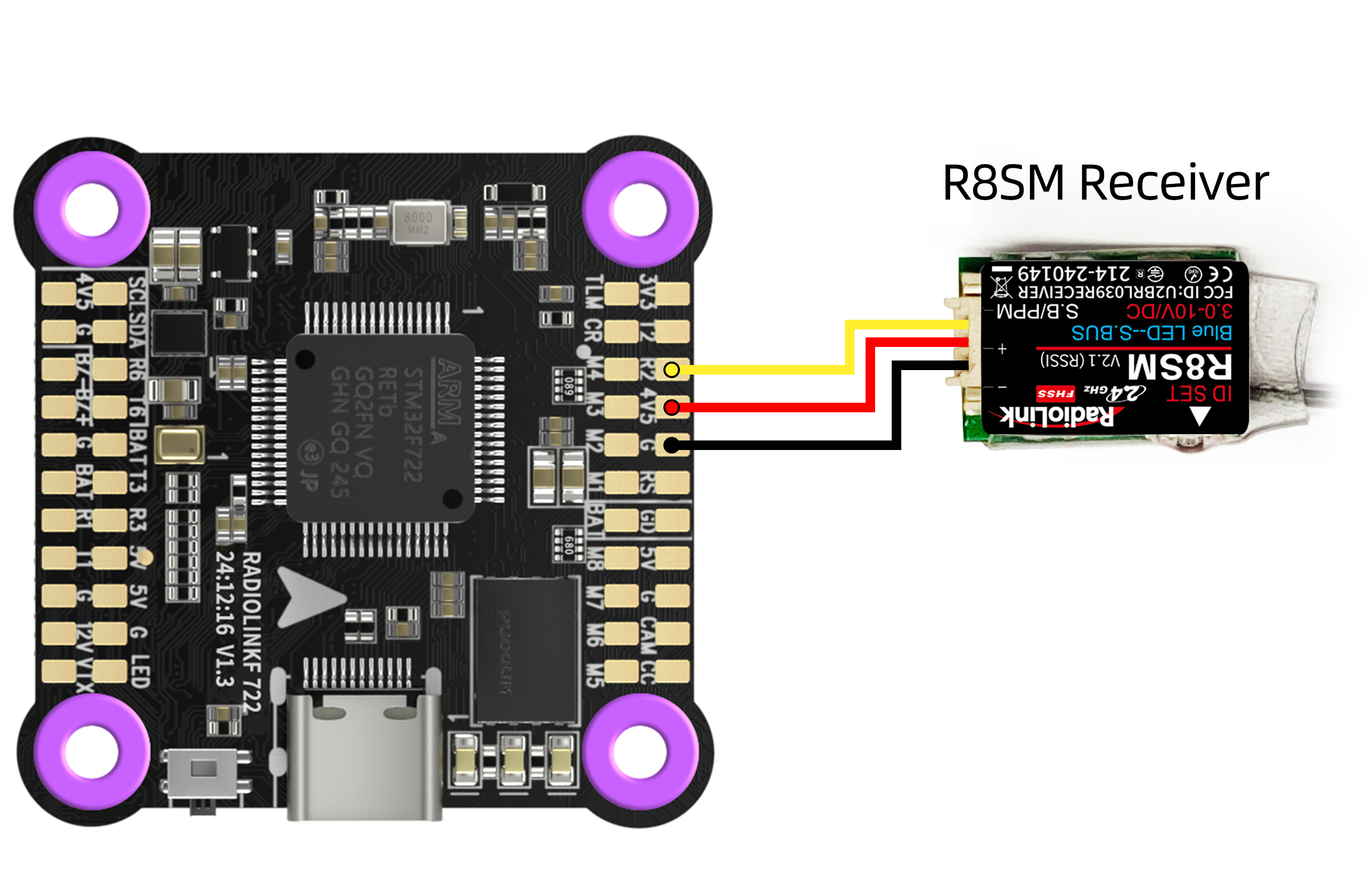
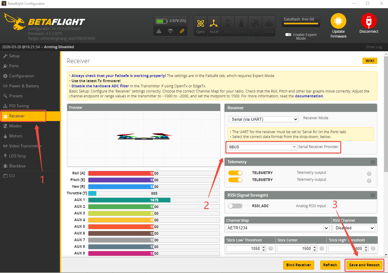
If SBUS receiver is used with LD-A40, please connect or solder SBUS receiver to the SBUS signal port of the flight controller (as shown below. RadioLink R8SM receiver is used as an example). Ensure that the receiver's SBUS signal wire is connected to the R2 of the flight controller. Then connect the flight controller to Betaflight Configurator. After the connection, click Ports, turn on the Serial RX of UART2 and click Save and Reboot. Then click Receiver, set SBUS for Serial Receiver Provider, and save the modifications. The steps are shown below:
13. Mode Setting
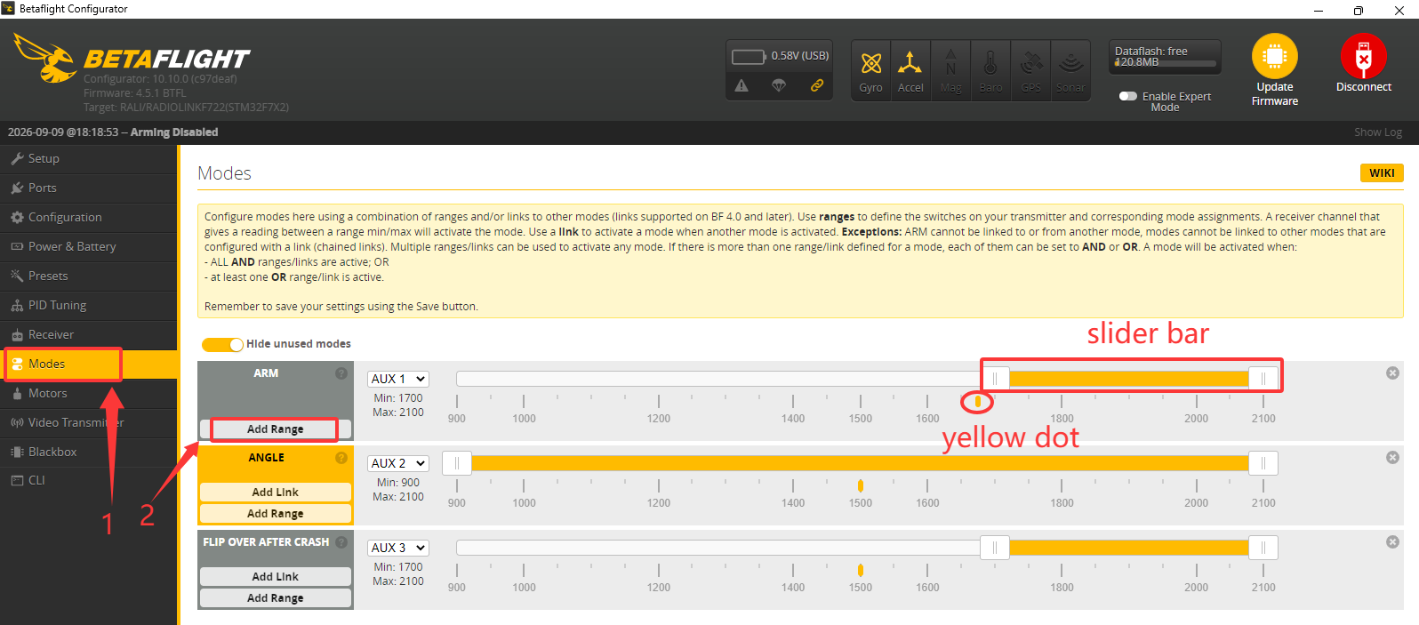
Click Mode on Betaflight Configurator to set the common functions of the flight controller by using the channels 5 through 12 (or even more). For the "ARM", click "Add Range" and set the option in the right-hand box to "AUTO." Then, toggle any switch on your transmitter; the flight controller will automatically recognize it as the arm/disarm switch. As you toggle the switch, a small yellow dot will move accordingly. Position the yellow slider bar so that it covers the area where the yellow dot appears, which indicates the "armed" state. The area not covered by the yellow slider bar corresponds to the "disarmed" state. You can manually adjust the range of the yellow slider bar.
For the "ANGLE" (stabilize mode), click "Add Range" and select the switch using the same method as for "ARM." Note that since this drone does not use a video transmission system, you can simply extend the range bar to the maximum value. If the yellow dot falls into the blank area above the bar, the drone enters manual mode.
For "FLIP OVER AFTER CRASH" (turtle Mode), click "Add Range" and select the switch using the same method as for "ARM." When the yellow slider bar covers the position of the yellow dot, the drone enters turtle Mode.
14. Troubleshooting
Problems | Solutions |
Unable to arm the drone. | Check whether the servo value when the joystick is moved to its lowest and leftmost positions falls below the minimum threshold. |
The aircraft rolls after taking off. | The propellers or motors may be installed in wrong direction. Please adjust them and try again. |
There is an abnormal sound after the aircraft is armed. | Arm the drone and turn the propeller by hand to check whether there are any objects or parts interfering with the propeller. Remove the objects. |
The aircraft shakes after it is armed. | Check whether the propeller is intact. If not, please replace the propeller. |
The aircraft sways after takeoff. | Connect the flight controller to Betaflight Configurator and calibration the accelerometer. |
After taking off, the aircraft deflects in one direction. | Turn the trim button to set the trim value to 0. For more details, please refer to the manual of the transmitter. |