
R12DS
(FHSS and DSSS Spread Spectrum)
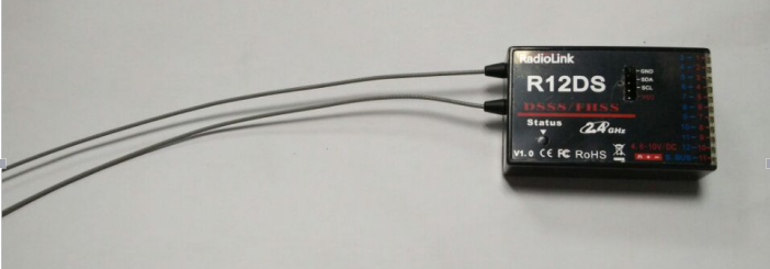
Radiolink R12DS, 2.4G 12 channels receiver, DSSS and FHSS spread spectrum working synchronously, compatible with Radiolink transmitters AT9, AT9S,AT9S Pro, AT10 and AT10II(AT9, AT9S, AT10 can upgrade to 12 channels just upgrade by firmware, you can download the firmware from our website: , AT9S Pro, AT10II is default 12 channels).
S-BUS and PWM signal possible working at the same time.
Two signal working mode:
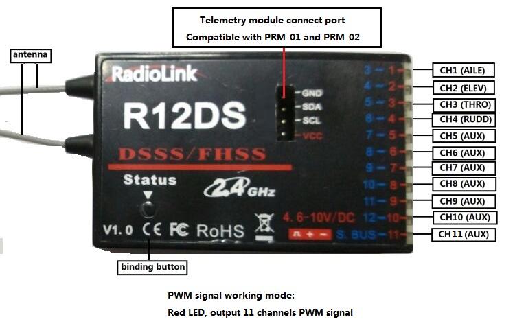
1. PWM signal output working mode
Red LED indicates PWM signal output, 11 channels totally.
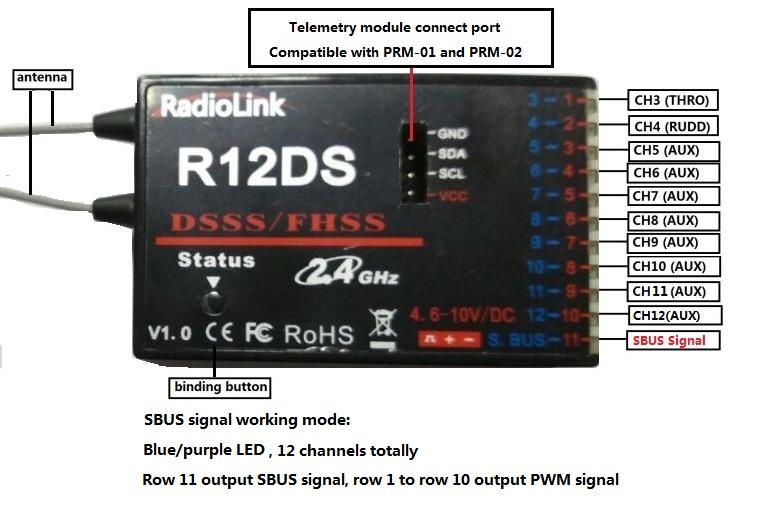
S-BUS signal working mode:
Blue/purple LED indicates S-BUS signal output, 12 channels totally.
S-BUS and PWM signal working at the same time. S-BUS signal channel (3 pin of row 11) output 12 channels S-BUS signal, PWM signal channels (3 pin of row 1 to row 10) output CH3 to CH12 PWM signals, 12 channels in total.
How many PWM signal channels you can use depends on how many S-BUS signal channels you have used (e.g.: you have use 4 SBUS signal channels, then you have 8 PWM signal channels to use).
SBUS and PPM signal change:
Short press the ID SET switch twice within 1 second, the signal is changed from PWM to SBUS. The red LED indicates the PWM and blue/purple indicates SBUS.
How to match code with transmitter:
1. Put the transmitter and the receiver close to each other within 50 centimeters.
2. Turn on the transmitter, then power on the R12DS.
3. Connect CH3 of R12DS to ESC or flight controller or servo.
4. There is a black button on the R12DS, use a thin stick or pen press the binding button in one second until the receiver light starts blinking and release, after about 8 times blinking, match code success when receiver signal LED always on.
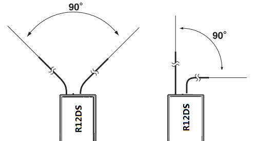
Installment of receiver antenna:
1.The antenna must be kept as straight as possible. Otherwise it will reduce the effective range.
2.Make the two antennas keep 90 degree.
3.Large model aircraft may have some metal part interfering signal; in this case the antennas should be placed at both sides of the model. Then the best RF signal condition is obtained at any flying attitude.
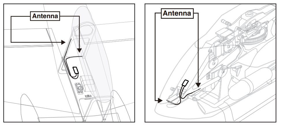
4.The antennas must be kept away from conductive materials, such as metal and carbon. at least a half inch. The coaxial part of the antennas does not need to follow these guidelines, but do not bend it in a small radius.
5.Keep the antennas away from the motor, ESC, and other noise sources as far as possible.
6.Press and hold the Easy Link (ID SET) one second, then the receiver starts work.
7.After all of the above steps were finished, the LED indicator will turn and keep in red.
8.The receiver can be packed by sponge or foam for shockproof when it is installed to the model.
After all of the above steps finished, now the program functions to assure it under control of transmitter with a right connection.
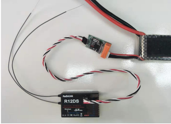
Connect to telemetry module PRM-01
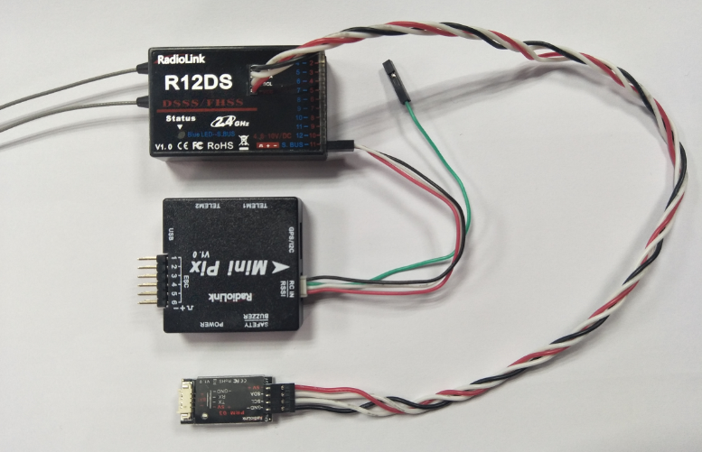
Connect to telemetry module PRM-03(the product in the middle is flight controller Mini Pix from Radiolink)
Specification:
Channels:
11 channels: output 11 channels signal when output PWM signal only.
12 channels: output 12 channels signal, support S-BUS and PWM signals output synchronously.
Working voltage: 4.8-10V
Working current: 38-45mA(input voltage: 5V)
Size: 50*31.5*14.5 mm
Weight: 14g
Receiver integrate telemetry sensor including signal strength and voltage. Support extended engine voltage telemetry module PRM-01 and module PRM-02 can feedback GPS info, Speed, voltage etc. on AT9/AT9S/AT10/AT10II display when work with flight controller APM or PIX.
4096 section precision, 0.25us per section, servo anti-shake rudder.
Control distance: about 4 kilometers air (Maximum range tested in unobstructed areas free of interference and may vary depending on local regulations).